
Operations Guide, Fourth Edition - HP Integrity rx1620
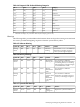

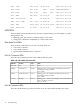

0060 - SFW Boot start 00-1D:0A:00 2003-10-31 22:39:05
0070 2 CPU1 Boot start 00063 DT 04 0000000000000000
0080 2 CPU1 Boot start 00063 Time 2003-10-31 22:39:05
0090 - BMC LPC reset 00-12:70:02 2003-10-31 22:39:07
00A0 - SEL Time Set Set FD-C0:03:01 2003-10-31 22:39:15
00B0 - Fan 2 (Mem) Fail (crit) 12-0A:07:02 2003-10-31 22:39:24
00C0 - BMC Chass cntrl 00-12:70:A3 00:E2 2003-10-31 22:39:31
00D0 - ACPI State S5 (off) FA-22:6F:05 2003-10-31 22:39:32
LAN LEDs
The front panel LAN LED indicates the system is communicating over the Gigabit or system
management LAN:
• Blinking green, the system is communicating over the LAN.
• Solid green, LAN link is established, no current LAN activity.
Rear Panel LAN LEDs
There are three LAN connectors on the rear panel. They are:
• 1Gb LAN A connector
• 1Gb LAN B connector
• Optional MP 10/100Mb LAN C connector
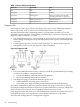
LAN A Connector LEDs
The 1Gb LAN A interface provides four LEDs on the rear panel:
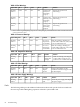
Table 4-22 1Gb LAN A Connector LEDs
StateColorLocationLAN LED
NoneNoneTopNot used
Blinking amber – the 1000 Mbps with ethernet protocol and
twisted-pair wiring is enabled.
Off – no link.
Amber2nd from top1000mb
Blinking green – the 100 Mbps with ethernet protocol and
twisted-pair wiring is enabled.
Off – no link.
Green2nd from bottom100mb
Blinking green – The Activity LED lights, and all other LEDs are
off for a 10 Mbps connection.
Off – no activity
GreenBottomActivity
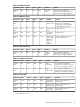
LAN B Connector LEDs
The 1Gb LAN B interface provides two LEDs on the rear panel (the left LED is not used):
90 Troubleshooting