
Windows Integrity Cluster Installation and Configuration Guide


Setup, configuration, validation, and maintenance of the cluster
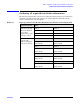
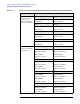
Verifying minimum software and hardware requirements
Chapter 2
22
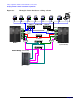
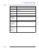
Figure 2-1 Example cluster hardware cabling scheme
FC Switch-1
Switch-1 Switch-2
Port- 1
Port- 2Port- 2
Port- 1
Public LAN
ComputerComputer Computer Wo r ks t a t io n Workstation Wo r ks t a t io nComputer
Client
ClientClientClientClient
ClientClient
NIC-1
NIC-2
NIC-1
NIC-2
Private LAN
Team
Team
MultiPath
FC Switch-2
MultiPath
Shared Storage
Node 1
FC
HBA
FC
HBA
`
PDC
Node “n”
(EVA, XP, MSA)
(up to 8 nodes total )