
Installation Guide, Third Edition - HP Integrity rx2620 (August 2006)


Chapter 3
Installing Additional Components
Installing Additional System Memory
42
NOTE DIMMs match if they have the same HP part number. The DIMMs are 184-pin,
industry-standard, DDR266, CL2, registered ECC modules. Industry standard means the
DIMMs meet specifications detailed in the JDEC Standard No. 21-C, Module 4, titled “PC2100
and PC1600 DDR SDRAM Registered DIMM Design Specification.” A complete and current list
of acceptable DIMMs is provided on the parts website at: http://partsurfer.hp.com.
You can mix module sizes, as long as DIMMs in each quad match, unless you are using 4 GB DIMMs. If you
install 4 GB DIMMS, the only configurations allowed are four or eight 4 GB DIMMs. For example:
• On HP Integrity rx2620 servers, it is acceptable to load a quad of 256 MB DIMMs in quad 1 (slots 0A, 0B,
1A and 1B), and a quad of 1 GB DIMMs in quad 2 (slots 2A, 2B, 3A and 3B).
• If using 4 GB DIMMs, the only configurations allowed are:
— Four 4 GB DIMMs in quad 1 (slots 0A, 0B, 1A, 1B), quad 2 (slots 2A, 2B, 3A, and 3B) and quad 3 (slots
4A, 4B, 5A, and 5B) remain empty
— Eight 4 GB DIMMs in quad 1 and quad 2, with quad 3 empty.
The memory subsystem supports chip-spare functionality. Chip spare enables the server to bypass an entire
SDRAM chip on a DIMM (logically replaced) in the event that a multi-bit error is detected on that SDRAM.
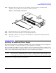
In order to use the chip spare functionality, use only DIMMs built with x4 SDRAM parts, You must load these
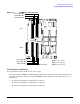
DIMMs in quads. See Figure 3-9 for the DIMM quads on the system board.
Each DIMM within a quad must be identical to all the other DIMMs in the quad.
To install DIMMs, perform the following steps:
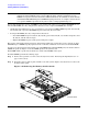
Step 1. Remove the top metal cover if it is not already removed. See “Removing the Top Metal Cover” on
page 35 if necessary.
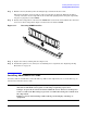
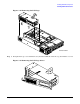
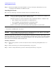
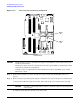
Step 2. Grasp the memory airflow guide and lift it out of the system. Figure 3-10 shows how to remove the
memory airflow guide.
Figure 3-10 Removing the Memory Airflow Guide
Front of server