
Installation Guide, Third Edition - HP Integrity rx2620 (August 2006)


Chapter 3
Installing Additional Components
Installing an Additional Processor
49
Installing an Additional Processor
This section provides information about installing processors. The processors are located on the system board,
accessible by removing the top metal cover.
WARNING Ensure that the system is powered down and all power sources have been
disconnected from the server prior to removing or replacing a processor.
Voltages are present at various locations within the server whenever an AC power
source is connected. This voltage is present even when the main power switch is in
the off position.
Failure to observe this warning could result in personal injury or damage to
equipment.
CAUTION Failure to properly complete the steps in this procedure will result in erratic system behavior
or system failure. For assistance with this procedure contact your local HP Authorized Service
Provider.
Observe all ESD safety precautions before attempting this procedure. Failure to follow ESD
safety precautions might result in damage to the server.
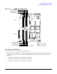
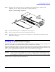
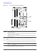
Processors are located on the system board. The system board can support either one or two processor. The
CPU 0 socket is located to the right of the system board (closer to the server chassis) and the CPU 1 socket is
located on the left of the system board near the memory DIMMs. In a single CPU configuration, you must
install the single processor in the CPU 0 socket. The load order is CPU 0, then CPU 1.
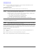
Figure 3-17 and Figure 3-18 show the processor locations).
Figure 3-17 Processor Location
CPU 0
CPU 1
Front of server