
HP Integrity rx2660 Server User Service Guide

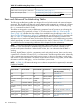
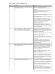
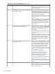
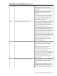
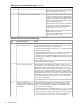

Table 33 Troubleshooting Entry Points (continued)
Subsection or LocationEntry Point
“Troubleshooting Tools” (page 111)Offline and Online Diagnostics/INIT button
“Troubleshooting Tools” (page 111) (see also http://
h18023.ww1.hp.com/support/svctools/webes for more information
about this tool)
System Event Analyzer (SEA)
Basic and Advanced Troubleshooting Tables
The following troubleshooting tables are designed for use by both trained and untrained support
personnel. They should be the first tool used to determine the symptom(s) or condition of a suspect
server. Be aware that the state of the front panel LEDs can be viewed locally, or remotely (using
the vfp command from the iLO 2 MP).
The tables are designed to cover troubleshooting symptoms from AC power-on up to booting the
operating system (OS), specifically in Steps 1-5. In most cases, the Table 34: “Front Panel LED
States” (page 106) identifies the step number where troubleshooting should begin in the Table 35:
“Basic Low End Troubleshooting” (page 107). Alternatively, you can skip Table 34, and start with
Step 1 in Table 35, sequencing through the table steps to locate the symptom/condition most
descriptive of your current server status; this becomes the first step in your troubleshooting procedure.
Where appropriate, an action or actions prescribed in the “Action” column of Table 35 is followed
by a reference to the corresponding subsection of this chapter for further information.
NOTE: In the table which follows, the Unit Identifier (UID)/locator LED has not been included,
because it is not used directly for troubleshooting rx2660 servers. However, indirectly, it can
provide useful system information. When the UID is blue, this is an indication that the BMC is
working.
Similarly, the INIT Button, which is a momentary switch with pinhole access, that is used to cause
a system INIT or Transfer of Control (ToC), is not discussed in the following tables either. It basically
is like a system reset, preserving the entire memory image, so that you can obtain a crash dump
and receive OS error information. This button can be used to recover a hung system, and to obtain
information useful for debugging -- it is less harsh than a power reset.
NOTE: In Table 34, LED states indicating error conditions are provided in uppercase (for example,
FLASHING AMBER).
Table 34 Front Panel LED States
Basic Low End Troubleshooting
Table Step Number
System PowerExternal HealthInternal HealthSystem Health
1 in Table 35OffOffOffOff
2a in Table 35STEADY AMBEROffOffOff
2b/2c in Table 35Steady greenFLASHING
AMBER
Off or steady greenFLASHING AMBER
OR RED
8b in Table 36Steady greenSteady greenFLASHING AMBEROff
3a/3b in Table 35Steady greenSteady greenFLASHING AMBERFLASHING AMBER
OR RED
4a, 4b, 4c, and 4d in Table 35Steady greenSteady greenSteady greenOff
8a in Table 36Steady greenSteady greenSteady greenSteady green/off
5, 6, and 7 in Table 35 and
Table 36
Steady greenSteady greenSteady greenSteady green
106 Troubleshooting