
HP Integrity rx2660 Server User Service Guide


WARNING! Ensure that the system is powered off and all power sources are disconnected from
the server prior to performing this procedure.
Voltages are present at various locations in the server whenever an AC power source is connected.
These voltages are present even when the main power switch is in the off position.
Failure to observe this warning can result in personal injury or damage to equipment.
CAUTION: Ensure that processor speeds and cache sizes are identical for all processors. Failure
to observe this caution causes performance degradation or system failure.
The easiest way to ensure processor compatibility is to use processors with identical part numbers.
CAUTION: Observe all ESD safety precautions before attempting this procedure. Failure to follow
ESD safety precautions can result in damage to the server.
Processor Load Order
The server supports up to two processors on the processor board. The slots on the processor board
are labeled CPU 0 and CPU 1. In single-processor servers, you must install the processor in the
CPU 0 slot. In dual-processor servers, you must install the second processor in the CPU 1 slot.
Table 66 Processor Load Order
SlotProcessor
CPU 01
CPU 12
Required Tools
To install and remove processors, use the processor install tool fastened to the airflow guide.
Removing a Processor
To remove a processor:
1. Power off the server and disconnect the power cables. See “Powering On and Powering Off
the Server” (page 77).
2. If rack mounted, slide the server out from the rack until it stops. See “Extending the Server
from the Rack” (page 141).
3. Remove the top cover. See “Removing the Top Cover” (page 142).
4. Remove the airflow guide. See “Removing the Airflow Guide” (page 143).
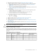
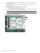
5. Open the processor cage.
a. Grasp the processor cage handle and apply adequate force to rotate the handle upward.
See Figure 64.
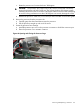
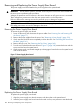
b. Use the handle to rotate the cage closure approximately 90 degrees toward the front of
the server until it stops. See Figure 65.
IMPORTANT: Ensure the processors are entirely exposed and can clear the cage
enclosure for removal.
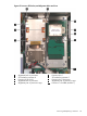
6. Disconnect the processor power cable from the connector cable attached to the system board.
See Figure 66.
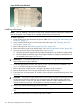
7. Unlock the processor from the socket on the processor board. See Figure 67.
a. Unfasten the processor installation tool (2.5 mm driver) from the tool holder on the airflow
guide.
b. Insert the processor tool into the hole on the side of the heatsink.
172 Removing and Replacing Server Components