
HP Integrity rx2660 Server User Service Guide
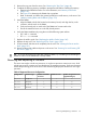


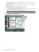


12. Align the alignment holes on the processor with the alignment posts on the processor cage,
and carefully lower the processor onto the processor socket. See Figure 67.
CAUTION: Do not press the processor into the socket. When properly aligned, the processor
pins seat into the socket. No additional pressure is required. Damage to the pins can occur
if pressure is applied.
13. Lock the processor into the socket on the processor board. See Figure 67.
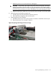
a. Unfasten the processor install tool (2.5 mm driver) from the tool holder on the airflow
guide.
b. Insert the processor tool into the hole on the side of the heatsink.
c. Rotate the processor tool clockwise 180 degrees.
CAUTION: The processor zero insertion force (ZIF) socket is locked and unlocked by
turning the processor tool half of a full turn. The counter-clockwise 180 degree rotation
(half turn) unlocks the socket. A clockwise 180 degree rotation locks the socket. Attempting
to turn the locking mechanism more than 180 degrees can severely damage the socket.
d. Fasten the processor install tool (2.5 mm driver) to the tool holder on the airflow guide.
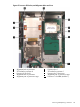
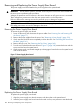
14. Connect the processor power cable into the connector cable that attaches directly to the
processor board. See Figure 66.
15. Close the processor cage. See Figure 65.
a. Grasp the processor cage handle and rotate the cage closure inward toward the rear of
the assembly until it is completely closed.
b. Apply adequate force to push the handle down until it is flush with the cage.
16. Replace the airflow guide. See “Replacing the Airflow Guide” (page 145).
17. Replace the top cover. “Replacing the Top Cover” (page 142).
18. If rack mounted, slide the server completely into the rack. See “Inserting the Server into the
Rack” (page 141).
19. Reconnect the power cables and power on the server. See “Powering On and Powering Off
the Server” (page 77).
20. Verify processor replacement and operation by using the system utilities.
• Use the iLO 2 MP SS command to verify operation
• Use the EFI info cpu command to verify operation
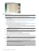
Removing and Replacing the Power Supply Housing
The power supplies seat into a housing that attaches to the system board through the power supply
riser board.
WARNING! Ensure that the system is powered off and all power sources are disconnected from
the server prior to performing this procedure.
Voltages are present at various locations in the server whenever an AC power source is connected.
These voltages are present even when the main power switch is in the off position.
Failure to observe this warning can result in personal injury or damage to equipment.
CAUTION: Observe all ESD safety precautions before attempting this procedure. Failure to follow
ESD safety precautions can result in damage to the server.
Removing the Power Supply Housing
To remove the power supply housing:
Removing and Replacing the Power Supply Housing 177