
HP Integrity rx2660 Server User Service Guide


1. To insert the TPM:
a. Align the TPM connector pinouts with the pins on the system board socket.
NOTE: The female connector on the TPM has one pinout plugged, which aligns with a
missing pin on the male connector on the system board.
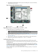
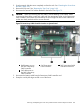
b. Push the TPM straight down into the socket until it is fully seated. See Figure 78.
2. Replace the top cover. See “Replacing the Top Cover” (page 142).
3. If rack mounted, slide the server completely into the rack. See “Inserting the Server into the
Rack” (page 141).
4. Reconnect the power cables and power on the server. See “Powering On and Powering Off
the Server” (page 77).
5. To enable the TPM:
a. Access the EFI Shell.
b. Enter info sec to display the server security settings on the screen. The TPM is disabled
by default.
c. Enter secconfig to display a list of configurable security settings.
d. Enter secconfig tpm on to enable the TPM.
6. Reset the server.
7. Boot the operating system. See Chapter 4 (page 85).
8. Restore the former TPM settings to the new TPM. See the operating system documentation for
more information.
9. Back up the TPM security information. See the operating system documentation for more
information.
CAUTION: When a TPM is installed and enabled on the server, data access is locked if you fail
to follow the proper procedures for updating the system or option firmware, replacing the system
board, replacing a hard drive, or adjusting the OS application TPM usage.
For more information on firmware updates and hardware procedures, see the HP Trusted Platform
Module Best Practices White Paper on the HP website: http://www.hp.com/support.
Removing and Replacing the Smart Array P400 Controller and PCIe
Expansion Board
The rx2660 server has two slots on the system board for the optional Smart Array P400 controller,
and the PCIe expansion board. The PCIe expansion board enables the Smart Array P400 controller
slot.
WARNING! Ensure that the system is powered off and all power sources are disconnected from
the server prior to performing this procedure.
Voltages are present at various locations in the server whenever an AC power source is connected.
These voltages are present even when the main power switch is off.
Failure to observe this warning can result in personal injury or equipment damage.
CAUTION: Observe all ESD safety precautions before attempting this procedure. Failure to follow
ESD safety precautions can result in damage to the server.
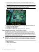
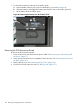
Removing the Optional Smart Array P400 Controller and Battery
To remove the optional Smart Array P400 controller:
1. Power off the server and disconnect the power cables. See “Powering On and Powering Off
the Server” (page 77).
188 Removing and Replacing Server Components