
HP Integrity rx2660 Server User Service Guide

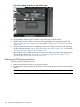


1. Insert the new system board with the back of the system board going into the server first.
Guide the system board onto the guide pins, and slide the system board into the keyways.
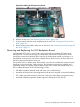
NOTE: When replacing the system board you are prompted to copy the secondary UUID
to the primary location (SEC to PRI). Reply y. (
2. Reconnect the cables that attach to the system board (1). See Figure 85.
3. Replace the I/O fan carrier. See “Replacing the I/O Fan Carrier Assembly” (page 163).
4. Reconnect the power cable that attaches to the SAS backplane.
5. Replace the Smart Array P400 controller backplane and PCIe expansion card (if necessary).
6. Reconnect the power cable that attaches to the Smart Array P400 controller backplane and
the PCIe expansion card (if necessary).
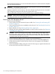
7. Reconnect the internal SAS cables.
CAUTION: When reconnecting the SAS cables, match each cable with the appropriate
socket on the SAS core I/O card. If the cables are mismatched, the server might not reboot.
Both cables and sockets are clearly marked with the correct channel.
NOTE: The cables connect directly to the system board for a non-RAID configuration, and
connect to the Smart Array P400 controller for a RAID configuration.
8. Replace the TPM. See “Replacing the TPM” (page 187).
9. Replace the I/O card cage. “Replacing the I/O Backplane Assembly” (page 165).
10. Replace the power supply cage. See “Replacing the Power Supply Housing” (page 179).
11. Replace the processors. See “Installing a Processor” (page 176).
12. Replace the memory. See “Installing Memory” (page 170).
13. Replace the airflow guide. See “Replacing the Airflow Guide” (page 145).
14. Replace the fan carrier assembly. “Replacing the Fan Carrier Assembly” (page 160).
15. Replace the top cover. See “Replacing the Top Cover” (page 142).
16. If rack mounted, slide the server completely into the rack. See “Inserting the Server into the
Rack” (page 141).
17. Reconnect all cables and power on the server. See “Powering On and Powering Off the
Server” (page 77).
18. Restore boot, LAN, and iLO 2 MP settings recorded in step Step 1 of the procedure, see
“Removing the System Board” (page 196) when prompted by the server.
Removing and Replacing the System Board 199