
HP Integrity rx2660 Server User Service Guide
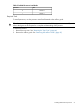
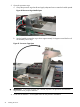
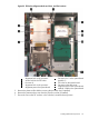
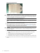
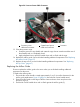
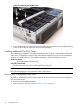

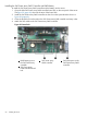

Figure 22 ZIF Socket, Alignment Holes and Posts, and Slot Locations
6
Processor slot 1 on the system board
(Module 1)
1
Alignment hole on the processor
2
Access hole for the ZIF socket
7
ZIF socket on the system board
3
Processor 0
8
Processor socket dust cover
4
Alignment hole on the processor
9
Alignment post on the system board
5
Alignment post on the system board
10
Module 1 label on the system board
5. Remove the plastic airflow blocker covering the processor slot (if installed).
6. Remove the protective dust cover from the processor socket (if installed).
7. Ensure the cam on the ZIF socket is in the unlocked, counterclockwise position.
Installing Additional Components 53