HP Smart Array 6400 Series Controllers for Integrity Servers User Guide August 2005 (Second Edition) Part Number 365510-002
© Copyright 2004, 2005 Hewlett-Packard Development Company, L.P. The information contained herein is subject to change without notice. The only warranties for HP products and services are set forth in the express warranty statements accompanying such products and services. Nothing herein should be construed as constituting an additional warranty. HP shall not be liable for technical or editorial errors or omissions contained herein. Microsoft and Windows are U.S.
Contents Hardware features ........................................................................................................................ 5 Board components .................................................................................................................................... 5 Expansion module components ................................................................................................................... 6 Controller specifications and attributes .......................
Cache module LEDs ................................................................................................................................. 31 Diagnostic tools ...................................................................................................................................... 32 Electrostatic discharge ................................................................................................................. 33 Preventing electrostatic discharge .............................
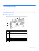
Hardware features In this section Board components ................................................................................................................................... 5 Expansion module components .................................................................................................................. 6 Controller specifications and attributes........................................................................................................
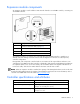
Expansion module components An expansion module is used to add two extra external channels to an SA6402 controller, converting it to an SA6404 controller. Item ID Description 0–7 Runtime LEDs (CR10–CR17). These are identical to the controller board runtime LEDs (on page 30). 8 VHDCI connector, port B2 9 VHDCI connector, port B1 10 Connector to controller board The expansion module is a controller in its own right.
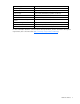
RAID levels supported 0, 1, 1+0, 5, ADG Processor type PowerPC 405 at 266 MHz DDR SDRAM bus transfer rate Up to 2.0 GB/s at 266 MHz (DDR, 72 bit) Connector type 3.3-V, 64-bit, Wide PCI-X (compatible with PCI slot) PCI-X transfer rate Up to 1.
Overview of the installation procedure In this section Quick installation procedure (Windows or Linux) ......................................................................................... 8 Quick installation procedure (Windows or Linux) Before installing the controller, refer to the support matrix on the HP website (http://www.hp.com/products1/serverconnectivity) to confirm that the server and operating system support the controller. To install the controller: 1. Power down the server. 2.
3. When you have finished installing the operating system as directed during the Express Setup procedure, remove the operating system CD and insert the Smart Setup media. 4. Install the Integrity Support Pack ("Installing device drivers and Management Agents" on page 17). Controller installation is complete.
Installing the controller hardware In this section Before beginning the installation .............................................................................................................. 10 Preparing the server ............................................................................................................................... 10 Installing the controller board ..................................................................................................................
1. Remove or open the access panel. 2. Select an available 3.3-V PCI or PCI-X slot. 3. If the controller is being hot-plugged, power down the slot. 4. Remove the slot cover or open the hot-plug latch. Save the retaining screw if one is present. 5. Slide the controller board along the slot alignment guide, and press the board firmly into the slot so that the contacts on the board edge are properly seated in the system board connector. 6.
4. For each SCSI bus, manually set the SCSI ID on each drive to a unique value in the range of 0 to 15, except 7 (which is reserved for controller use). For detailed instructions, consult the documentation that is provided with the drive. 5. Attach a multi-device SCSI cable from the internal connector of the controller to the non-hotpluggable hard drives. (The cable might have been provided with the server.) 6. Replace the access panel, and secure it with the thumbscrews if any are present.
Updating the firmware In this section Methods for updating the firmware (Windows® or Linux®)......................................................................... 13 Methods for updating the firmware (Windows® or Linux®) To update the firmware on the server, controller, or hard drives, use Smart Components. The most recent version of a particular component is available on the support page of the HP website (http://www.hp.com/support). Some components are also available on the Smart Setup media. 1.
Configuring an array In this section Introduction ........................................................................................................................................... 14 Comparing the utilities ............................................................................................................................ 14 Using ORCA.......................................................................................................................................... 15 Using ACU .....
Supported features ACU ORCA Suitable for configuration while offline -- + Supported procedures ACU ORCA Creation and deletion of arrays and logical drives + + Assignment of RAID level + + Sharing of spare drives among several arrays + -- Assignment of multiple spare drives per array + -- Setting of stripe size + -- Migration of RAID level or stripe size + -- Configuration of controller settings + -- Expansion of an array + -- Creation of multiple logical drives per array +
5. Press the Enter key to continue. You can now create another logical drive by repeating the previous steps. NOTE: Newly created logical drives are invisible to the operating system. To make the new logical drives available for data storage, format them using the instructions given in the operating system documentation. Using ACU For detailed information about using ACU, refer to the HP Array Configuration Utility User Guide.
Installing device drivers and Management Agents In this section Systems using Microsoft Windows............................................................................................................ 17 Systems using Linux®..............................................................................................................................
3. Power up the system. As Linux boots, it recognizes the controller. 4. Enter one of the following commands as appropriate to ensure that the driver is loaded correctly: Red Hat: #mkinitrd -f /boot/efi/efi/redhat/initrd-$(uname -r).img $(uname -r) Novell (SLES): #mkinitrd -k /boot/vmlinux -i/boot/initr 5. For Novell, enter the following command to confirm that the driver is active: #lsmod | grep cciss If the driver is active, the system responds by displaying cciss.
Upgrading or replacing controller options In this section Replacing a battery ................................................................................................................................ 19 Replacing the expansion module.............................................................................................................. 20 Replacing a battery WARNING: There is a risk of explosion, fire, or personal injury if the battery pack is not properly handled.
b. Lift the battery pack off the cache board (2). 4. Remove the secondary cache battery pack: a. Unhook the wire retainer that holds the battery pack to the controller board (1). b. While holding the battery in one hand, pull the plastic retainer tabs up and push them through to the other side of the controller board (2). 5. Replace whichever battery is degraded. 6. Reinstall the batteries on the cache board and the controller board. 7. Reinstall the cache board and its battery on the controller.
2. Press firmly on the back of the expansion module to seat the expansion module connector securely in the socket on the controller board (3). 3. Secure the expansion module to the controller board by inserting and tightening the appropriate screw (provided in the kit) in the back of the controller board (4). To remove the expansion module, reverse this procedure.
Replacing, moving, or adding hard drives In this section Identifying the status of a hard drive ......................................................................................................... 22 Recognizing hard drive failure ................................................................................................................. 23 Replacing hard drives .............................................................................................................................
Activity LED (1) Online LED Fault LED (2) (3) Interpretation On or flashing Flashing Do not remove the drive. Removing a drive may terminate the current operation and cause data loss. Off The drive is rebuilding or undergoing capacity expansion. On Off Off Do not remove the drive. The drive is being accessed, but (1) it is not configured as part of an array; (2) it is a replacement drive and rebuild has not yet started; or (3) it is spinning up during the POST sequence.
• RAID 0 configurations cannot tolerate drive failure. If any physical drive in the array fails, all nonfault-tolerant (RAID 0) logical drives in the same array will also fail. • RAID 1+0 configurations can tolerate multiple drive failures as long as no failed drives are mirrored to one another. • RAID 5 configurations can tolerate one drive failure. • RAID ADG configurations can tolerate simultaneous failure of two drives.
automatically (as indicated by the blinking Online LED on the replacement drive) if the array is in a faulttolerant configuration. If you replace a drive belonging to a fault-tolerant configuration while the system power is off, a POST message is displayed when the system is next powered up. This message prompts you to press the F1 key to start automatic data recovery.
If another drive in the array fails while fault tolerance is unavailable during rebuild, a fatal system error may occur, and all data on the array is then lost. In exceptional cases, however, failure of another drive need not lead to a fatal system error.
2. Replace any drive. The data on the new drive is recreated from redundant information on the remaining drives. CAUTION: Do not replace any other drive until data rebuild on this drive is complete. 3. When data on the new drive has been rebuilt (the Activity LED turns off), repeat the previous step for the other drives in the array, one at a time. When you have replaced all drives, you can use the extra capacity to either create new logical drives or extend existing logical drives.
c. Open ACU and navigate to the controller that contained the RAID ADG volume. ACU displays the missing RAID ADG volume using a different icon to indicate that the volume is unavailable. d. Delete the RAID ADG volume. e. Accept the configuration change, and then close ACU. f. Power down the system. 4. Move the drives. 5. Power up the system. If a 1724 POST message is displayed, drive positions were changed successfully and the configuration was updated.
When the expansion process has finished, you can use the liberated storage capacity on the enlarged array to create new logical drives. Alternatively, you can enlarge one of the original logical drives. This latter process is called logical drive capacity extension and is also carried out using ACU.
Diagnosing array problems In this section Controller board runtime LEDs.................................................................................................................. 30 Cache module LEDs................................................................................................................................ 31 Diagnostic tools .....................................................................................................................................
LED ID Color LED name and interpretation 8 Amber CR11: Battery Status LED. For interpretation, refer to Cache module LEDs (on page 31). 9 Green CR10: Battery Charging LED. For interpretation, refer to Cache module LEDs (on page 31).
Item 1 (amber LED) Item 2 (green LED) Slow blink (once every 16 seconds) Interpretation This display pattern might occur after the system is powered down. It indicates that the cache contains data that has not yet been written to the drives. Restore system power as soon as possible to prevent data loss. (The battery lifetime depends on the cache module size. For further information, refer to the controller QuickSpecs on the HP website (http://www.hp.com).
Electrostatic discharge In this section Preventing electrostatic discharge............................................................................................................. 33 Grounding methods to prevent electrostatic discharge ................................................................................ 33 Preventing electrostatic discharge To prevent damaging the system, be aware of the precautions you need to follow when setting up the system or handling parts.
Regulatory compliance notices In this section Federal Communications Commission notice ............................................................................................. 34 Canadian notice (Avis Canadien) ............................................................................................................ 35 European Union regulatory notice ............................................................................................................
energy and, if not installed and used in accordance with the instructions, may cause harmful interference to radio communications. However, there is no guarantee that interference will not occur in a particular installation.
Class B equipment This Class B digital apparatus meets all requirements of the Canadian Interference-Causing Equipment Regulations. Cet appareil numérique de la classe B respecte toutes les exigences du Règlement sur le matériel brouilleur du Canada.
BSMI notice Japanese notice Korean notice A&B Class A equipment Class B equipment Regulatory compliance notices 37
Battery replacement notice This component uses a nickel metal hydride (NiMH) battery pack. WARNING: There is a risk of explosion, fire, or personal injury if a battery pack is mishandled. To reduce this risk: • Do not attempt to recharge the batteries if they are disconnected from the controller. • Do not expose the battery pack to water, or to temperatures higher than 60°C (140°F). • Do not abuse, disassemble, crush, or puncture the battery pack. • Do not short the external contacts.
Acronyms and abbreviations ACU Array Configuration Utility ADG Advanced Data Guarding (also known as RAID 6) ADU Array Diagnostics Utility DIMM dual inline memory module EBSU EFI-based setup utility EFI extensible firmware interface ESD electrostatic discharge EULA end user license agreement OEM original equipment manufacturer ORCA Option ROM Configuration for Arrays PCI-X peripheral component interconnect extended POST Power-On Self Test Acronyms and abbreviations 39
RAID redundant array of inexpensive (or independent) disks RBSU ROM-Based Setup Utility SA Smart Array SIM Systems Insight Manager VHDCI very high density cable interconnect Acronyms and abbreviations 40
Index extending logical drive capacity 28 A ACU (Array Configuration Utility) 16 adding drives 28 array capacity expansion 28 array controller installation overview 8 array, configuring 14 automatic data recovery (rebuild) 24, 25, 26 F failure of hard drive 23, 26 fault tolerance, compromised 24 Federal Communications Commission (FCC) notice 34, 35 firmware, updating 13 B G batteries, replacing 19 battery replacement notice 38 board components 5 BSMI notice 37 grounding methods 33 C cables 35 cache m
O ORCA (Option ROM Configuration for Arrays) 15 overview of installation process 8 P POST error messages 23 power requirements 6 R rebuild, time required for 25, 26 regulatory compliance notices 34, 36 replacing hard drives 22, 24 replacing the batteries 19 ROM, updating 13 S specifications, controller 6 static electricity 33 status lights, cache module 31 status lights, controller 30 status lights, hard drive 22 storage devices, connecting 11 storage, external 12 T Taiwan battery recycling notice 38 tr