
HP Smart Array 6400 Series Controllers for Integrity Servers User Guide

Diagnosing array problems 30
Diagnosing array problems
In this section
Controller board runtime LEDs.................................................................................................................. 30
Cache module LEDs................................................................................................................................ 31
Diagnostic tools ..................................................................................................................................... 32
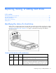
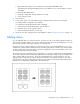
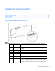
Controller board runtime LEDs
NOTE: During server power-up, each runtime LED illuminates randomly until POST has finished.
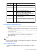
LED ID Color LED name and interpretation
0 Amber CR100: Diagnostics Error LED.
1 Amber
CR101: Drive Failure LED. A physical drive connected to the controller
has failed.
2 Blue
CR102: SCSI Bus Active LED. At least one of the SCSI buses on the
controller is active.
3 Green CR103: XOR Active LED. The controller is calculating parity data.
4 Green
CR104: Command Outstanding LED. The controller is working on a
command.
5 Blue
CR105: Heartbeat LED. This LED flashes every 2 seconds, unless the
controller is malfunctioning.
6 Green
CR106: Gas Pedal LED. This LED, together with item 7, indicates the
amount of controller CPU activity. For details, refer to the following table.
7 Green
CR107: Idle Task LED. This LED, together with item 6, indicates the
amount of controller CPU activity. For details, refer to the following table.