HP AD397A rx2660 SAS Smart Array P400 Controller Installation Guide Manufacturing Part Number: AD397-9001A February 2007 United States © Copyright 2007 Hewlett-Packard Development Company L.P..
Legal Notices The information in this document is subject to change without notice. Hewlett-Packard makes no warranty of any kind with regard to this manual, including, but not limited to, the implied warranties of merchantability and fitness for a particular purpose. Hewlett-Packard shall not be held liable for errors contained herein or direct, indirect, special, incidental or consequential damages in connection with the furnishing, performance, or use of this material.
Contents 1. Installing the SAS Smart Array P400 Controller Overview of Installation Steps . . . . . . . . . . . . . . . . . . . . . . . . . . . . . . . . . . . . . . . . . . . . . . . . . . . . . . . . . . 5 Installing the Smart Array Controller . . . . . . . . . . . . . . . . . . . . . . . . . . . . . . . . . . . . . . . . . . . . . . . . . . . . 6 Power Off the Server. . . . . . . . . . . . . . . . . . . . . . . . . . . . . . . . . . . . . . . . . . . . . . . . . . . . . . . . . . . . . . . . .
Contents 4
1 Installing the SAS Smart Array P400 Controller This chapter provides information to help you plan the installation and configuration of each Smart Array Controller.
Installing the SAS Smart Array P400 Controller Installing the Smart Array Controller Installing the Smart Array Controller The rx2660 server has two slots dedicated for the SAS Smart Array P400 controller and PCI-e expansion card. Use these procedures to install these cards on the system board.
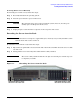
Installing the SAS Smart Array P400 Controller Installing the Smart Array Controller Powering Off the Server Manually To manually power off the server, follow these steps: Step 1. Gracefully shut down the operating system. Step 2. Press the power button to power off the server. CAUTION The main DC voltage is now removed from the system; however, AC voltage for standby power is still present in the server. Step 3. Unplug all power cables from the receptacles on the rear panel of the server.
Installing the SAS Smart Array P400 Controller Installing the Smart Array Controller Removing the Top Cover When installing internal components into the server, you must first remove the top cover. To remove the top cover, follow these steps: Step 1. Unlock the cover release lever (if necessary) by turning the cam approximately 90 degrees counterclockwise with the allen wrench provided on the rear panel of the server (1). Step 2.
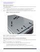
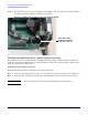
Installing the SAS Smart Array P400 Controller Installing the Smart Array Controller Figure 1-3 Removing the I/O Backplane Card Cage Captive screws Front of server Step 2. Lift the assembly straight up and out of the server. Step 3. Disconnect the SAS cables connected to the system board, and remove the cables from the two routing clips on the server chassis. See Figure 1-4. Step 4. Route the cables through the unused clip against the server chassis back panel.
Installing the SAS Smart Array P400 Controller Installing the Smart Array Controller Step 5. Check that the cables are routed around the I/O backplane card cage connector, so that they will not be pinched when the backplane assembly is re-installed.
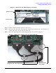
Installing the SAS Smart Array P400 Controller Installing the Smart Array Controller Figure 1-6 SAS Smart Array P400 Controller and PCI-e Expansion Board Slots 1 2 1 Card locking guides PCI-e expansion card (in slot) Front of server SAS smart array P400 controller card slot Step 3. Close the board locking guides to lock the PCI-e expansion card into place on the system board.
Installing the SAS Smart Array P400 Controller Installing the Smart Array Controller Figure 1-7 SAS Ports on the Smart Array P400 Controller Board Memory card installed on P400 controller card B SAS ports on the SAS Smart Array P400 controller card A SAS Smart Array P400 controller card Card lock (open) Step 3. Install the SAS Smart Array P400 controller card into the slot on the system board as shown in Figure 1-7. Step 4.
Installing the SAS Smart Array P400 Controller Installing the Smart Array Controller a. Align the tabs on the P400 controller battery with the slots on the airflow guide. b. Slide the P400 controller battery toward the rear of the server until the locking clip locks the P400 controller battery in place. Figure 1-8 Installing the RAID battery Battery cable plugged into battery 1 Step 2. Plug the battery cable into the battery. See Figure 1-8. Step 3. Plug the battery cable into the P400 controller card.
Installing the SAS Smart Array P400 Controller Installing the Smart Array Controller Replacing the I/O Backplane Card Cage To replace the I/O backplane card cage into the server, follow these steps: Step 1. Align the tabs with the guide slots in the server and slide the I/O backplane assembly into place. See Figure 1-3. Ensure the I/O backplane card cage is fully seated into the server. If the I/O backplane card cage is not fully seated, the server may not boot.
Installing the SAS Smart Array P400 Controller Checking and Updating Smart Array P400 Controller Firmware Checking and Updating Smart Array P400 Controller Firmware Follow the procedures in this section to verify that the correct adapter firmware version is installed before you attempt to boot the server. Firmware version requirements are found in the HP Smart Array RAID Controllers Support Matrix in the “Smart Array (RAID)” section of: http://docs.hp.com/en/netcom.
Installing the SAS Smart Array P400 Controller Checking and Updating Smart Array P400 Controller Firmware fs0:\EFI\TOOLS> saupdate list ******************************************************************************** Smart Array Offline Firmware Update Utility Version 2.06.10.03 (C) Copyright 2006 Hewlett-Packard Development Company, L.P. ******************************************************************************** Seg 0 Bus 52 Dev 0 Func 0 Description HP Smart Array P400 Version 2.
Installing the SAS Smart Array P400 Controller Checking and Updating Smart Array P400 Controller Firmware Step 4. Locate the cdrom entry in the list of mapped devices, and change to the device by typing its associated fs number (for example, fs0) under EFI Shell prompt. Step 5. If the EFI utility and firmware image files are not located in the root directory, move to the directory in which these files are located, for example: fs0:\>cd \EFI\HP\TOOLS\IO_CARDS\SmartArray IMPORTANT Both saupdate.
Installing the SAS Smart Array P400 Controller Checking and Updating Smart Array P400 Controller Firmware Verifying the Firmware Update After updating the firmware, cycle the power on the system and on any external JBODS connected to the system. After performing the firmware update, use LIST to confirm that the correct firmware version is installed; see “Checking the Controller Firmware” on page 15.
Installing the SAS Smart Array P400 Controller Creating Logical Drives Creating Logical Drives This section describes the steps to create logical drives for a Smart Array Series Controller using the Option ROM Configuration for Arrays (ORCA) utility. ORCA Utility To use ORCA, follow these steps: Step 1. Power on the server. POST runs, and any array controllers that are in the server are initialized one at a time.
Installing the SAS Smart Array P400 Controller Creating Logical Drives Step 2. Use the Arrow keys, Spacebar, and Tab to navigate around the screen and set up the logical drive, including an online spare drive if one is required. NOTE You cannot use ORCA to configure one spare drive to be shared among several arrays. Only ACU enables you to configure shared spare drives. Step 3. Press Enter to accept the settings. Step 4. Press F8 to confirm the settings and save the new configuration.
A Smart Array P400 Controller Overview This chapter describes the board components, features, and diagnostic LEDs on the Smart Array P400 Controller.
Smart Array P400 Controller Overview Board Components and Features Board Components and Features Two models of the HP Smart Array P400 Controller are available. One model has the internal Serial-Attached SCSI (SAS) connectors on the front of the board; see Figure A-1. The other model has the connectors on the back of the board; see Figure A-2 on page 23. The two models have identical functionality.
Smart Array P400 Controller Overview Board Components and Features Figure A-2 HP Smart Array P400 Controller with SAS Connectors on Back Table A-2 Components of the HP Smart Array P400 Controller with SAS Connectors on Back Item ID Description 1 Connectors for cache module (also known as BBWC or array accelerator) 2 SAS or SATA port 1I (internal), 4x wide SFF8484 connector. 3 Runtime LEDs. See “Controller Board Runtime LEDs” on page 24.
Smart Array P400 Controller Overview Board Components and Features Controller Board Runtime LEDs The Smart Array P400 Controller board has eight runtime LEDs that indicate various activities and error conditions. Figure A-3 illustrates their location, and Table A-3 describes how to interpret them. Figure A-3 Smart Array P400 Controller Board Runtime LEDs Table A-3 Interpretation of Runtime LEDs LED ID Color Name LED Name and Interpretation 1 Amber CR14 Controller lockup LED.
Smart Array P400 Controller Overview Board Components and Features Table A-4 LED 7 Status Determining the Controller CPU Activity Level LED 8 Status Controller CPU Activity Level Off Blinking 0 to 25% Blinking Off 25 to 50% On Steady Off 50% to 75% On steady On Steady 75% to 100% NOTE Appendix A During server power on, each runtime LED illuminates randomly until POST completes.
Smart Array P400 Controller Overview Board Components and Features Battery Pack LEDs The battery pack has four runtime LEDs that indicate battery readiness and error conditions. Figure A-4 illustrates their location; Table A-5 and Table A-6 describe how to interpret them. Figure A-4 Smart Array P400 Battery Pack LEDs Table A-5 Battery Pack LEDs LED Color Description 1 Green System Power LED. This LED glows steadily when the system is powered up and 12 V system power is available.
Smart Array P400 Controller Overview Board Components and Features Table A-6 Interpreting Battery Pack LEDs LED 3 State LED 4 State Interpretation -- One blink every two seconds The system is powered down, and the cache contains data that has not yet been written to the drives. Restore system power as soon as possible to prevent data loss. Data preservation time is extended any time that 3.3 V auxiliary power is available, as indicated by LED 2.
Smart Array P400 Controller Overview Board Components and Features 28 Appendix A
B Fault Management This Appendix provides an overview of the fault management features of the HP Smart Array P400 Controller.
Fault Management Fault Management Features Fault Management Features The Smart Array P400 Controller supports several fault management and data reliability features that minimize the impact of disk drive defects on your systems. Auto-Reliability Monitoring (ARM) A firmware process that operates in the background, scanning physical disks for bad sectors in fault-tolerant logical drives. ARM also verifies the consistency of parity data in logical drives that use RAID 5 or RAID ADG.
Fault Management Fault Management in Supported RAID Configurations Fault Management in Supported RAID Configurations If a physical disk fails in RAID 1, RAID 1+0, RAID 5, or ADG, the system will still process I/O requests, but at a reduced performance level. Replace the failed physical disk as soon as possible to restore performance and full fault tolerance for the logical drive it belongs to.
Fault Management Fault Management in Supported RAID Configurations 32 Appendix B
C Declaration of Conformity Appendix C 33
Declaration of Conformity Figure C-1 34 Smart Array P400 Declaration of Conformity Appendix C