
Installation Guide - HP AD397A rx2660 SAS Smart Array P400 Controller

Installing the SAS Smart Array P400 Controller
Installing the Smart Array Controller
Chapter 1
14
Replacing the I/O Backplane Card Cage
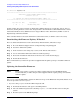
To replace the I/O backplane card cage into the server, follow these steps:
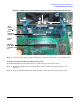
Step 1. Align the tabs with the guide slots in the server and slide the I/O backplane assembly into place.
See Figure 1-3.
NOTE Ensure the I/O backplane card cage is fully seated into the server. If the I/O
backplane card cage is not fully seated, the server may not boot.
Ensure the SAS cables are not pinched under the I/O backplane card cage when
installing it into the server. The SAS cables should be routed to the right of the I/O
backplane card cage.
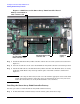
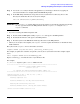
Step 2. Tighten the two captive screws.
a. Press the black knob down while turning it clockwise until it is fully tightened.
b. While holding the black knob and pressing down, press and release the blue button to lower the
black knob to the locked position.
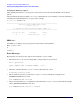
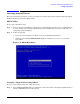
Replacing the Top Cover
To replace the top cover, follow these steps:
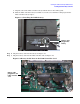
Step 1. Ensure the cover release lever is in the open position. See Figure 1-10.
Step 2. Align the tabs of the top cover with the corresponding slots in the chassis and insert the tabs into
the slots (1).
Step 3. Slide the cover forward until it is flush with the front of the chassis (2).
Step 4. Push the cover release lever down into the latched position (3).
Step 5. Lock the cover release lever (if necessary) by turning the cam approximately 90 degrees clockwise.
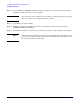
Figure 1-10 Replacing the Top Cover
1
3
2