
Installation Guide - HP AD397A rx2660 SAS Smart Array P400 Controller

Smart Array P400 Controller Overview
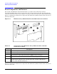
Board Components and Features
Appendix A
24
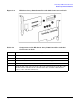
Controller Board Runtime LEDs
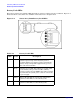
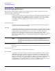
The Smart Array P400 Controller board has eight runtime LEDs that indicate various activities and error
conditions. Figure A-3 illustrates their location, and Table A-3 describes how to interpret them.
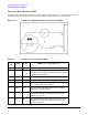
Figure A-3 Smart Array P400 Controller Board Runtime LEDs
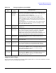
Table A-3 Interpretation of Runtime LEDs
LED
ID
Color Name LED Name and Interpretation
1 Amber CR14 Controller lockup LED.
2 Amber CR13 Disk Failure LED. A physical disk connected to the
controller has failed. Check the Fault LED on each disk
to identify the failed disk.
3 Green CR3 Activity LED for SAS port 2I.
4 Green CR8 Activity LED for SAS port 1I.
5 Green CR5 Command Outstanding LED. The controller is working
on a command from the host driver.
6 Green CR6 Heartbeat LED. This LED blinks every 2 seconds to
indicate the controller health.
7 Green CR4 Gas Pedal LED. This LED, together with item 8 (CR7),
indicates the amount of controller CPU activity. See
Table A-4 on page 25.
8 Green CR7 Idle Task LED. This LED, together with item 7 (CR4),
indicates the amount of controller CPU activity. See
Table A-4 on page 25.