
Installation Guide - HP AD397A rx2660 SAS Smart Array P400 Controller


Smart Array P400 Controller Overview
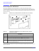
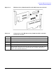
Board Components and Features
Appendix A
26
Battery Pack LEDs
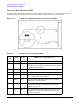
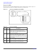
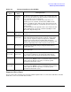
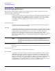
The battery pack has four runtime LEDs that indicate battery readiness and error conditions. Figure A-4
illustrates their location; Table A-5 and Table A-6 describe how to interpret them.
Figure A-4 Smart Array P400 Battery Pack LEDs
Table A-5 Battery Pack LEDs
LED Color Description
1 Green System Power LED. This LED glows steadily when the
system is powered up and 12 V system power is
available. This power supply is used to maintain the
battery charge and provide supplementary power to
the cache microcontroller.
2 Green Auxiliary Power LED. This LED glows steadily when
3.3V auxiliary voltage is detected. The auxiliary
voltage is used to preserve BBWC data and is available
any time that the system power cords are connected to
a power supply.
3 Amber Battery Health LED. To interpret the illumination
patterns of this LED, see the following table.
4 BBWC Status LED. To interpret the illumination
patterns of this LED, see the following table.