
HP Integrity rx2660 Server User Service Guide

21
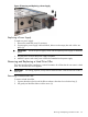
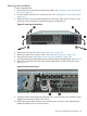
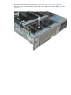
T-10 bezel screw locationSystem Insight Display
power cable (disconnected
from fan/display board)
Replacing the Front Bezel
To replace the front bezel:
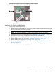
1. Guide the power connector on the System Insight Display through the hole in the server chassis.
See Figure 53.
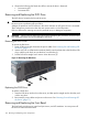
2. Align the bezel slots with the tabs on the server, and rotate the bezel downward and gently
push it into place so it is flush with the front server wall.
3. Replace the screws that attaches the bezel to the server.
4. Connect the System Insight Display power cable to the fan/display board.
5. Replace the fan carrier into the server. See “Replacing the Fan Carrier Assembly” (page 160).
6. Replace the system fans. See “Replacing a Server Fan ” (page 149).
7. Replace the top cover. See “Replacing the Top Cover” (page 142).
8. If rack mounted, slide the server completely into the rack. See “Inserting the Server into the
Rack” (page 141).
9. Reconnect the power cables and power on the server. See “Powering On and Powering Off
the Server” (page 77).
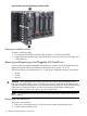
Removing and Replacing the System Insight Display
The System Insight Display is located in the front of the server and is attached to the front bezel.
WARNING! Ensure that the system is powered off and all power sources are disconnected from
the server prior to performing this procedure.
Voltages are present at various locations in the server whenever an AC power source is connected.
These voltages are present even when the main power switch is off.
Failure to observe this warning can result in personal injury or equipment damage.
CAUTION: Observe all ESD safety precautions before attempting this procedure. Failure to follow
ESD safety precautions can result in damage to the server.
Removing the System Insight Display
To remove the System Insight Display:
1. Power off the server and disconnect the power cables. See “Powering On and Powering Off
the Server” (page 77).
2. If rack mounted, slide the server completely out from the rack. See “Extending the Server from
the Rack” (page 141).
3. Remove the top cover. See “Removing the Top Cover” (page 142).
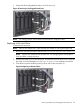
4. Remove the front fan carrier assembly. See “Removing the Fan Carrier Assembly” (page 158).
5. Disconnect the System Insight Display power cable from the fan/display board.
6. Remove the front bezel from the server. See “Removing the Front Bezel” (page 155)
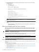
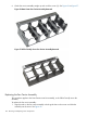
7. Push on the two plastic clips that hold the System Insight Display to the bezel (1) and push the
System Insight Display through the front of the bezel.
156 Removing and Replacing Server Components