
HP Integrity rx2660 Server User Service Guide

2. Rotate the fan carrier assembly handle downward approximately 90 degrees until it closes
flush against the airflow guide.
3. Install the fans in to the fan carrier. See “Replacing a Server Fan ” (page 149).
4. Replace the top cover. See “Replacing the Top Cover” (page 142).
5. If rack mounted, slide the server completely into the rack. See “Inserting the Server into the
Rack” (page 141).
6. Reconnect the power cables and power on the server. See “Powering On and Powering Off
the Server” (page 77).
Removing and Replacing the I/O Fan Carrier Assembly
The server contains an I/O fan carrier assembly, located behind the SAS backplane, that houses
four of the 12 server fans in the Data Center server, or two of the six fans if you have an Office
Friendly Server.
WARNING! Ensure that the system is powered off and all power sources are disconnected from
the server prior to performing this procedure.
Voltages are present at various locations in the server whenever an AC power source is connected.
These voltages are present even when the main power switch is in the off position.
Failure to observe this warning can result in personal injury or damage to equipment.
CAUTION: Observe all ESD safety precautions before attempting this procedure. Failure to follow
ESD safety precautions can result in damage to the server.
Removing the I/O Fan Carrier Assembly
This procedure applies to both the Data Center server and Office Friendly server.
To remove the I/O fan carrier assembly:
1. Power off the server and disconnect the power cables. See “Powering On and Powering Off
the Server” (page 77).
2. If rack mounted, slide the server completely out from the rack. See “Extending the Server from
the Rack” (page 141).
3. Remove the top cover. See “Removing the Top Cover” (page 142).
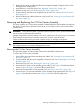
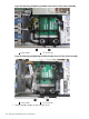
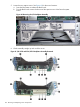
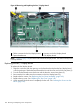
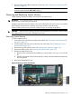
4. Disconnect the I/O fan carrier assembly power cable (1). See Figure 58 for the Data Center
server, or Figure 59 (page 162) for the Office Friendly server.
5. Remove the fans from the I/O fan assembly. See “Removing a Server Fan” (page 147).
6. Loosen the four T-15 screws that hold the I/O fan assembly to the system board. See Figure 58
(page 162) for the Data Center server, or Figure 59 for the Office Friendly server.
Removing and Replacing the I/O Fan Carrier Assembly 161