
HP Integrity rx2660 Server User Service Guide

Removing and Replacing the Fan / Display Board
The fan/display board is a combination board that provides and supports the following
functionalities:
• Fan power for the server fans
• Power switch and status LEDs
• DVD drive
• Front panel USB port
• Front panel VGA port
The fan/display board contains the power switch and the following status LEDs:
• Power LED
• System health LED
• Internal health LED
• External health LED
• Locator (UID) LED
WARNING! Ensure that the system is powered off and all power sources are disconnected from
the server prior to performing this procedure.
Voltages are present at various locations in the server whenever an AC power source is connected.
These voltages are present even when the main power switch is in the off position.
Failure to observe this warning can result in personal injury or damage to equipment.
CAUTION: Observe all ESD safety precautions before attempting this procedure. Failure to follow
ESD safety precautions can result in damage to the server.
NOTE: The fan/display board includes a USB connector that supports USB 2.0 (480 Mbps) and
a VGA connector.
The fan/display board is also the secondary location of the UUID for the server. Do not remove
the system board and fan/display board at the same time, or the UUID is deleted from the server.
The procedure for removing the fan/display board for the Data Center server is the same for the
Office friendly server.
Removing the Fan / Display Board
To remove the fan/display board:
1. Power off the server and disconnect the power cables. See “Powering On and Powering Off
the Server” (page 77).
2. If rack mounted, slide the server completely out from the rack. See “Extending the Server from
the Rack” (page 141).
3. Remove the top cover. See “Removing the Top Cover” (page 142).
4. Remove the server fans in the fan carrier. See “Removing a Server Fan” (page 147).
5. Remove the front fan carrier assembly. See “Removing the Fan Carrier Assembly” (page 158).
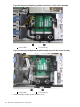
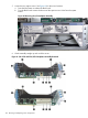
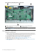
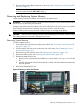
6. Disconnect the five cables attached to the fan/display board (1). See Figure 62.
7. Turn the captive knurled thumb screws counterclockwise until the screws release from the server
(2).
8. Shuttle the board toward the rear of the server until the board keyways clear the server guide
pins (3). Tilt the board toward the front of the server, and lift it out at an angle (4).
Removing and Replacing the Fan / Display Board 167