
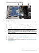
HP Integrity rx2660 Server User Service Guide

1. Save your system configuration and iLO 2 MP configuration settings.
IMPORTANT: Before removing the system board, record all boot configuration settings (find
the settings using the INFO ALL EFI command). You must reset these values after replacing
the battery. Use the LS EFI command to gather the LAN configuration information.
You can also use the non-volatile RAM configuration backup (NVRAM) backup utility to back
up and store these values. The utility is located on the HP website at http://www.hp.com/go/
bizsupport.com.
For iLO 2 MP configuration settings, see the HP Integrity iLO 2 Operations Guide.
2. Power off the server and disconnect the power cables. See “Powering On and Powering Off
the Server” (page 77).
3. Disconnect all external cables from the server rear panel.
4. If rack mounted, slide the server completely out from the rack. See “Extending the Server from
the Rack” (page 141).
5. Remove the top cover. See “Removing and Replacing the Top Cover” (page 142).
6. Remove the fan carrier. See “Removing the Fan Carrier Assembly” (page 158).
7. Remove the airflow guide. See “Removing the Airflow Guide” (page 143).
8. Remove the memory. See “Removing System Memory” (page 169).
9. Remove the processors. See “Removing a Processor ” (page 172).
10. Remove the power supply housing. See “Removing the Power Supply Housing” (page 177).
11. Remove the I/O backplane assembly. See “Removing the I/O Backplane Assembly” (page 163).
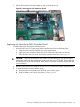
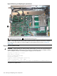
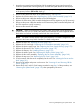
12. Disconnect the internal SAS cables attached to the system board (if necessary. See Figure 85.
CAUTION: When disconnecting the SAS cables, note the labeling on the cables. When
reconnecting these cables, match each cable with the appropriate socket on the SAS core
I/O card. If the cables are mismatched, the server might not reboot. Both the cables and the
sockets are clearly marked with the correct channel.
NOTE: The cables connect directly to the system board for a non-RAID configuration, and
connect to the Smart Array P400 controller board for a RAID configuration.
13. Remove the Trusted Platform module (if necessary). See “Removing the TPM” (page 187).
14. Disconnect the power cable that attaches the Smart Array P400 controller board to the battery
on the airflow guide (if necessary).
15. Remove the Smart Array P400 controller backplane and the PCIe expansion card (if necessary).
16. Remove the I/O fan carrier. See “Removing the I/O Fan Carrier Assembly” (page 161).
17. Disconnect the cables that attach to the system board (1). See Figure 85.
18. Pull up on the post in the center of the system board to unlock it from the server chassis. See
Figure 85.
19. Shuttle the system board toward the front of the server until the board keyways clear the server
guide pins. Tilt the system board toward the rear of the server and lift it out at an angle from
the server to remove it.
Removing and Replacing the System Board 197