HP Integrity rx2660 Server Installation Guide HP Part Number: AB419-9000C Published: November 2007
© Copyright 2007 Hewlett-Packard Development Company, L.P Legal Notices The information contained herein is subject to change without notice. The only warranties for HP products and services are set forth in the express warranty statements accompanying such products and services. Nothing herein should be construed as constituting an additional warranty. HP shall not be liable for technical or editorial errors or omissions contained herein. Printed in U.S.A.
Table of Contents About This Document.........................................................................................................9 Intended Audience.................................................................................................................................9 New and Changed Information in This Edition.....................................................................................9 Publishing History........................................................................
Installing the Server into a Rack......................................................................................................36 HP Rack......................................................................................................................................36 Non-HP Rack..............................................................................................................................36 Installing the Server Into a Pedestal.....................................................
List of Figures 1-1 1-2 1-3 1-4 1-5 1-6 1-7 1-8 1-9 1-10 1-11 1-12 1-13 1-14 1-15 1-16 1-17 1-18 1-19 1-20 1-21 1-22 1-23 1-24 Removing a Hard Drive Filler.......................................................................................................17 Installing a SAS Hard Drive..........................................................................................................18 Power Supply Location.............................................................................................
List of Tables 1 2 1-1 1-2 1-3 1-4 1-5 1-6 1-7 1-8 1-9 1-10 1-11 1-12 Publishing History Details..............................................................................................................9 HP-UX 11i Releases.......................................................................................................................11 Installation Sequence Checklist.....................................................................................................14 Memory Load Order...........
About This Document This document describes how to unpack the HP Integrity rx2660 server, install additional components, install the server into a standard rack or pedestal configuration, power on the server, and start a server console session. The document printing date and part number indicate the document’s current edition. The printing date changes when a new edition is printed. Minor changes may be made at reprint without changing the printing date.
Installation Sequence and Checklist Provides the installation sequence and an installation checklist. Unpacking and Inspecting the Server Provides information about unpacking and inspecting the server. Installing Additional Components Provides procedures on installing additional components purchased with the server that were not factory installed. Installing the Server Into a Rack or Pedestal Provides procedures to mount the server into a rack or pedestal configuration.
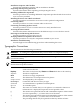
| Separates items in a list of choices. HP-UX Release Name and Release Identifier Each HP-UX 11i release has an associated release name and release identifier. Theuname (1)command with the-roption returns the release identifier. This table shows the releases available for HP-UX 11i. Table 2 HP-UX 11i Releases Release Identifier Release Name Supported Processor Architecture B.11.11 HP-UX 11i v1 PA-RISC B.11.20 HP-UX 11i v1.5 Intel® Itanium® B.11.22 HP-UX 11i v1.6 Intel Itanium B.11.
Send comments to: netinfo_feedback@cup.hp.com. Include the title, manufacturing part number, and any comment, error found, or suggestion for improvement you have concerning this document. Also, please include what we did right so we can incorporate it into other documents.
1 Installing the Server This chapter provides information and procedures for installing the HP Integrity rx2660 server.
Installation Sequence and Checklist Table 1-1 lists the server installation steps. Follow these steps in sequence to complete a successful installation. Table 1-1 Installation Sequence Checklist Step Description 1 Unpack and inspect the server shipping container. Inventory the contents using the packing slip. 2 Install any additional components shipped with the server. 3 Install the server into a rack or pedestal. 4 Connect cables to the server. Completed a: Connect ac input power cable.
For more information on server electrical, physical space, and environmental requirements, see the HP Integrity rx2660 Site Preparation Guide. Inspecting the Shipping Containers for Damage HP shipping containers protect their contents under normal shipping conditions. After the equipment arrives, carefully inspect each carton for signs of shipping damage. Shipping damage constitutes moderate to severe damage, such as punctures in the corrugated carton, crushed boxes, or large dents.
Installing Additional Components This section describes how to install components into the server that are not factory-installed. If you have additional components to install, be sure to install the additional components before installing the server into your rack or pedestal configuration. Most servers are pre-configured with all components installed prior to shipping from the HP factory.
2. Pull gently until the filler slides out of the server (2). Figure 1-1 Removing a Hard Drive Filler NOTE: SAS hard drives are loaded in order, starting with slot 8, going from right to left, to slot 1. Save the SAS hard drive filler for future use. For airflow purposes, always place hard drive fillers in slots that do not contain SAS disk drives. Installing a SAS Hard Drive To install a SAS hard drive, follow these steps. 1.
2. Close the drive extraction handle by pushing it downward until it clicks into place (2). Figure 1-2 shows how to install a SAS hard drive. Figure 1-2 Installing a SAS Hard Drive Installing a Hot-Swappable Power Supply The Data Center server has at least one hot-swappable power supply installed before shipping. This power supply is located at the rear of the server. You can install a second, optional power supply to provide 1+1 capability.
Figure 1-3 Power Supply Location 1 Power supply 1 2 Power supply 2 CAUTION: If you do not purchase a second power supply, the empty power supply slot must remain covered with the supplied metal filler panel. Failure to observe this caution can result in server shutdown due to overheating. Installing a Power Supply To install a power supply, follow these steps. 1. 2. Remove the metal slot filler by pulling it straight out of the server using the finger holes (1).
To remove the top cover, follow these steps. 1. 2. 3. 4. Unlock the cover release lever (if necessary) by turning the cam approximately 90 degrees counterclockwise with the Allen wrench provided on the rear panel of the server (1). Pull up on the cover release lever to disengage the top cover from the chassis (2). Slide the cover toward the rear of the server until the tabs release from the slots in the chassis (3). Lift the cover off the chassis (4).
2. If the RAID battery is connected to the airflow guide, remove it before removing the airflow guide. To remove the RAID battery, follow these steps: a. Pull the RAID battery lock away from the RAID battery (1). b. Slide the RAID battery toward the front of the server to disengage it from the airflow guide (2). c. Pull straight up on the RAID battery to remove it from the airflow guide. Figure 1-6 Removing the Airflow Guide 3.
4. Lift the airflow guide straight up and out of the server (2). Figure 1-7 shows the Data Center fan carrier. Figure 1-7 Fan Carrier Handle Installing System Memory The rx2660 server has eight system memory (DIMM) slots located on the system board. CAUTION: Observe all ESD safety precautions before attempting this procedure. Failure to follow ESD safety precautions can result in damage to the server.
The supported DIMM sizes for the server are as follows: • 512 MB • 1 GB • 2 GB • 4 GB Memory Pairs When installing memory, use a minimum of one pair of like-sized DIMMs. You can install additional DIMMs later. Install DIMMs into the appropriate slots on the system board; each slot has a unique ID. Figure 1-8 shows the DIMM slot IDs.
Installing Memory To install memory, follow these steps: 1. 2. 3. Remove the top cover from the server. See “Removing the Top Cover” (page 19). Remove the airflow guide. See “Removing the Airflow Guide” (page 20). Complete the following memory installation prerequisite tasks before installing the memory: a. Determine the DIMM load order. For more information, see “Memory Load Order” (page 23). b. See Figure 1-8 (page 23) to determine which DIMM slots to populate. c.
Table 1-3 rx2660 Processor Load Order Processor Slot 0 Module 0 1 Module 1 Required Tools To install processors, use the processor install tool fastened to the airflow guide. TIP: Prior to installing a processor into the server, read the following instructions carefully and refer to the figures in this section for a complete understanding of this process. To install a processor, follow these steps: 1. 2. Remove the top cover. See “Removing the Top Cover” (page 19) Remove the airflow guide.
3. Open the processor cage. a. Grasp the processor cage handle and apply adequate force to rotate the handle upward. Figure 1-9 shows the processor cage handle open. Figure 1-9 Processor Cage Handle b. Use the handle to rotate the cage closure approximately 90 degrees toward the front of the assembly until it stops. Figure 1-10 shows the processor cage fully open. Figure 1-10 Processor Cage Open IMPORTANT: Ensure the processor slot is entirely exposed.
Figure 1-11 shows the slot locations on the system board.
Figure 1-12 ZIF Socket CAUTION: The ZIF socket for the processor is locked and unlocked by half a full turn of the processor install tool. The counterclockwise 180 degree rotation (half turn) unlocks the socket. A clockwise 180 degree rotation locks the socket. Attempting to turn the locking mechanism more than 180 degrees can severely damage the socket. 8. Remove any protective packaging from the processor. NOTE: use. Protective covers are installed to protect connector pins.
Figure 1-13 Processor Power Connectors 1 Processor power cable and connector 2 System board power cable and connector 3 Processor 13. Close the processor cage. a. Grasp the processor cage handle and rotate the cage closure inward toward the rear of the assembly until it is completely closed. b. Apply adequate force to push the handle down until it is flush with the cage. 14. Replace the airflow guide if you are finished installing additional components. See “Replacing the Airflow Guide” (page 29).
Figure 1-14 Replacing the Airflow Guide 4. Ensure the fans have not become disconnected when opening the fan carrier handle by pushing down on all the fans to make sure they are seated properly. Installing Additional PCIe/PCI-X Cards The rx2660 server supports PCI-X cards and PCI-Express (PCIe) cards. There are three PCIe/PCI-X slots in the I/O backplane located on the system board.
2. Loosen the two captive screws on the I/O backplane assembly. Follow these steps to loosen the captive screws: a. Press the blue button to release the black knob. Figure 1-15 shows the location of the I/O backplane assembly captive screws. Figure 1-15 I/O Backplane Assembly Screw Locations b. Turn the black knob counterclockwise until the captive screw is free from the server.
3. Lift the assembly straight up and out of the server. NOTE: Depending on your configuration, you have one of the I/O backplane assemblies shown in Figure 1-16. The top I/O backplane assembly is a PCIe/PCI-X backplane assembly, and the bottom is a PCI-X backplane assembly.
3. Insert the PCIe/PCI-X card into the empty slot, and exert even pressure to seat the card in the slot. CAUTION: Ensure that you fully seat the card into the slot or the card can fail after power is applied to the slot. 4. 5. Close the gate latch to secure the end of the card if it is full length. Attach the PCIe/PCI-X card to the I/O backplane by tightening the T-15 screw on the I/O backplane.
Figure 1-17 SAS Smart Array P400 Controller and PCIe Expansion Board Slots NOTE: 3. The board and slot are keyed, so the board only fits one way into the slot. Close the board locking guides to lock the PCIe expansion board into place on the system board. Installing the SAS Smart Array P400 Controller and RAID Battery To install the SAS Smart Array P400 controller and the battery into the server, follow these steps: 1. 2. 3. 4.
3 SAS Smart Array 4 SAS cable ports on the RAID battery port on the SAS Smart Array P400 controller SAS Smart Array P400 controller controller 2 SAS Smart Array P400 controller board lock To install the RAID battery onto the airflow guide, follow these steps: a. Align the tabs on the RAID battery with the slots on the airflow guide. b. Slide the RAID battery toward the rear of the server until the locking clip locks the RAID battery in place (1). 1 5.
5. Lock the cover release lever (if necessary) by turning the cam approximately 90 degrees clockwise. Figure 1-20 shows how to replace the top cover. Figure 1-20 Replacing the Top Cover Installing the Server into a Rack or Pedestal This section provides instructions on how to install the server into a rack or a pedestal. Installing the Server into a Rack The following sections describe how to install the server into an HP rack or an approved non-HP rack.
To change the server from a rack mount to a rackless configuration, you need a Server Rackless Mount Kit. The rackless mount kit comes with the HP Integrity rx2660 Server Pedestal Installation Guide. Follow the steps in this installation guide to attach the pedestal to the server. Connecting the Cables This section describes the cables to connect to power the server and to provide LAN connectivity for the server. ac Input Power The server can receive ac input from two different ac power sources.
Figure 1-21 Rear Panel Control, Port, and LED Locations 1 2 3 4 5 Power supply 1 and LED Power supply 2 and LED PCI-X/PCIe slots Core LAN ports Smart Array P400 controller slot 6 7 8 9 Auxiliary serial port VGA port USB ports Console serial port 10 11 12 13 iLO 2 MP LAN port iLO 2 MP status LEDs iLO 2 MP reset UID button/LED NOTE: The Office Friendly server is shown in Figure 1-21 (page 38). The Data Center server may only have one power supply installed.
2. Connect the LAN cable from an available LAN port into a live connection on the network.
Setup Checklist Use the checklist in Table 1-5 to assist with the Integrity iLO 2 MP setup process. Table 1-5 Setup Checklist Step Action Standard Setup 1 Preparation 1. Determine an access method to select and connect the cables. 2. Determine a LAN configuration method and assign an IP address if necessary.
Setup Flowchart Use this flowchart as a guide to assist in the iLO 2 MP setup process.
Preparation You must perform the following tasks before you can configure the iLO 2 MP LAN. • Determine the physical access method to select and connect cables. • Determine the iLO 2 MP LAN configuration method and assign an IP address if necessary. Determining the Physical iLO 2 MP Access Method Before you can access the iLO 2 MP, you must first determine the correct physical connection method. The iLO 2 MP has a separate LAN port from the system LAN port.
Table 1-7 LAN Configuration Methods DHCP DNS RS-232 Serial Port (iLO LAN Configuration Method 2 MP LC command) Yes Yes No DHCP Yes Yes Yes DHCP, RS-232 serial port, or remote/modem port No No No ARP Ping No Yes No ARP Ping No Yes Yes ARP Ping, RS-232 serial port, or remote/modem port Yes No Yes RS-232 serial port, or remote/modem port No No Yes RS-232 serial port, remote/modem port, or ARP Ping Yes No No Cannot set up the LAN. Reconsider your criteria.
Configuring the iLO 2 MP LAN Using ARP Ping The Address Resolution Protocol (ARP) and Packet Internet Grouper (Ping) utility uses ARP packets to ping, or discover, a device on the local network segment. The IP address you assign to the server must use the same network segment, or subnet, as the computer assigning the address. ARP does not work across routed or switched networks.
6. At the DOS prompt, enter ping followed by the IP address to verify that the iLO 2 MP LAN port is configured with the appropriate IP address. The destination address is the IP address that is mapped to the iLO MAC address. Perform this task from the PC that has the ARP table entry. ping For example: ping 192.0.2.1 7. 8. Connect to the iLO 2 MP LAN using this IP address.
4. Connect the cables. a. Connect the DB-9 end of the RS-232 serial port female-to-female cable to the console RS-232 serial port. b. Connect the other end of the DB-9 female-to-female cable to the console device. 5. 6. 7. 8. Start the emulation software on the console device. Log in to the iLO 2 MP. See “Logging In to the iLO 2 MP” (page 46). At the MP Main Menu, enter CM and press Enter to select command mode. At the command mode prompt, enter LS and press Enter.
Additional Setup This section provides additional information to help you set up the iLO 2 MP. Modifying User Accounts and Default Password The iLO 2 MP comes preconfigured with default factory settings, including a default user account and password. The two default user accounts at initial login are as follows: • • All Rights (Administrator) level user: login = Admin password = Admin Console Rights (Operator) level user: login = Oper password = Oper NOTE: User account and password are case sensitive.
Security Access Settings CAUTION: When DHCP is enabled, the system is vulnerable to security risks because anyone can access the iLO 2 MP until you change the default user name and password. HP strongly recommends you assign user groups and rights before proceeding. Determine the security access required and user accounts and privileges needed. The iLO 2 MP provides options to control user access.
1. Open a web browser and enter the host name or the IP address for the iLO 2 MP. The iLO 2 MP Login page appears (Figure 1-23). Figure 1-23 iLO 2 MP Web Login Page 2. 3. Log in using your user account name and password. Click Sign In. The Status Summary page appears (Figure 1-24). Figure 1-24 Status Summary Page 4. 5. 6. Select the web interface functions by clicking the Function tabs at the top of the page. Each function lists options in the Navigation Bar on the left side of the page.
Accessing the Graphic Console Using VGA VGA is a method you can use to access the graphic console. NOTE: You cannot access the iLO 2 MP using VGA. This method requires three elements: • • • Monitor (VGA connector) Keyboard (USB connector) Mouse (USB connector) The graphic console output displays on the monitor screen. IMPORTANT: The server console output does not display on the console device screen until the server boots to the EFI Shell.
• • iLO 2 MP PC command Power button Powering On the Server Using the iLO 2 MP NOTE: If the power restore feature is set to Always On through the iLO 2 MP PR command, the server automatically powers on to the full power state when the power cord is plugged in to the server. To power on the server using the iLO 2 MP, follow these steps: 1. 2. 3. 4. 5. 6. Plug all power cables into the receptacles on the rear panel of the server. Initiate a console session, and access the MP Main Menu.
Powering Off the Server Manually To manually power off the server, follow these steps: 1. 2. Gracefully shut down the operating system. For information on how to shut down the operating system, see the HP Integrity rx2660 User Service Guide or your operating system documentation. Press the Power button to power off the server. CAUTION: The main dc voltage is now removed from the system; however, ac voltage for standby power is still present in the server. 3.
3. Enter info all from the EFI Shell prompt. The following displays: Shell> - - - - - - - - - - - - Live Console - - - - - - - - - - - info all SYSTEM INFORMATION Date/Time: Mar 6, 2007 13:00:10 (20:07:03:06:13:00:10) Manufacturer: hp Product Name: server rx2660 Product Number: AB419A Serial Number: US64293295 UUID: B6DDD02D-774F-11DB-8759-5250AF09A183 System Bus Frequency: 266 MHz PROCESSOR MODULE INFORMATION CPU Module -----0 # of Logical CPUs ------2 Speed -------1.
System Wake-On-LAN: Enabled BOOT INFORMATION Monarch CPU: Current Monarch CPU Module/ Logical ------0/0 Preferred Monarch CPU Module/ Logical --------0/0 Warnings -------- AutoBoot: OFF - Timeout is disabled Boottest: BOOTTEST Settings Default Variable OS is not speedy boot aware.
CHIP REVISION INFORMATION Chip Type ------------------Memory Controller Root Bridge Host Bridge Host Bridge Host Bridge Host Bridge Host Bridge Other Bridge Other Bridge Baseboard MC Logical ID ------0 0 0000 0002 0003 0006 0007 0 0 0 Device ID -----4032 4030 122e 122e 12ee 12ee 12ee 0 0 0 Chip Revision -------0020 0020 0032 0032 0011 0011 0011 0030 5003 0506 SYSTEM SECURITY CONFIGURATION Trusted Boot: Not Supported TPM: Activated TPM Next Boot Status: Activated TPM Vendor ID: 0x15D1 TPM Product ID: 0x0
the console. Additional information about troubleshooting is available on the CD provided with the server. Offline troubleshooting programs are available on the resource CD that is shipped with the server. To troubleshoot the server, you must be familiar with the Offline Diagnostics Environment (ODE) which runs in the Extensible Firmware Interface (EFI). Descriptions and user information about offline troubleshooting tools are available at http://www.docs.hp.com.
NOTE: If the server is off, and power is not connected to server power supplies, pressing the Power button has no effect. Power problems during installation are usually related to the installation process. If the server does not power on, check the LED indicators on the power supply rear panels and follow these steps. • • • If the ac power LED on the power supply on the rear panel of the server is lit, power is available to the server.
5. 6. Re-seat all main memory DIMMs. Re-seat all cable harnesses and board connectors. DVD Problems DVD problems that occur during installation are usually related to faulty connections. If you are experiencing DVD problems, follow these steps: 1. 2. 3. 4. Remove and reinsert the disk. Replace the disk. Remove and reinstall the DVD drive. Check that connectors are fully engaged. Replace the DVD drive.
1. 2. 3. 4. Initiate a server console session. Insert the CD with the copy of the latest version of the firmware. Using the EFI Boot Manager menu, boot to the drive that contains the CD with the updated firmware. Follow the instructions to update the firmware.
Index A ac power Data Center server, 37 input, 37 Office Friendly server, 37 ac power inputs A0, 37 A1, 37 B0, 37 B1, 37 audience, 9 C checklist, server installation, 14 CM command, 51 command mode (see CM) console problems occur, 58 console session determining connection method, 42 using VGA, 50 cover, top remove, 19 removing and replacing, 19 replace, 35 CPU (see processor) D DHCP and DNS, 43 defined, 43 DHCP-enabled security risk, 48 DNS defined, 43 Domain Name Server (see DNS) dual-core processing def
manually, 51 using the iLO 2 MP PC command, 51 PR command, 50 processor configuration options, 24 installing, 24 load order, 24 required service tools, 25 restrictions, 24 R Rack Installing Into, 36 Remove and Replace Hard Drive, Hot-Plug, 16 PCI/PCI-X Cards, 30 Power Supply, Hot-Swap, 18 S safety information, general, 13 security risk with DHCP enabled, 48 server installation checklist, 14 static IP address assigning with ARP Ping, 44 assigning with LC command, 45 T top cover (see cover, top) troublesho