HP Carrier-Grade rx2800 i2 Server DC Solution Installation Guide Abstract This document contains specific information that is intended for users of this HP product.
© Copyright 2011, 2012 Hewlett-Packard Development Company, L. P. Legal notices The information contained herein is subject to change without notice. The only warranties for HP products and services are set forth in the express warranty statements accompanying such products and services. Nothing herein should be construed as constituting an additional warranty. HP shall not be liable for technical or editorial errors or omissions contained herein.
Contents 1 Installing the server.....................................................................................5 Installation sequence and checklist..............................................................................................5 Installing the server into a seismic rack........................................................................................5 Hardware kit contents...........................................................................................................
Related documents.............................................................................................................24 Standard terms, abbreviations and acronyms..................................................25 Index.........................................................................................................
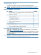
1 Installing the server This equipment is intended for installation in Network Telecommunication Facilities. CAUTION: Before starting this procedure, see “Preventing electrostatic discharge” (page 14). Installation sequence and checklist Step Description Completed 1 Perform site preparation (see the Site preparation chapter in the HP Carrier-Grade rx2800 i2 Server DC Solution User Service Guide. 2 Install the server into the rack. 3 Connect cables to the server. a.
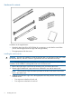
Hardware kit contents In addition to the supplied items: • If needed, obtain the HP kit (AT112-2100A) for connecting to a rack that has round holes. (The kit includes eight round hole cage nuts and eight screws.) • The appropriate tool for the screws. Installing the rack mount kit CAUTION: Plan the rack installation so that the heaviest item is on the bottom of the rack. Install the heaviest item first, and then continue to populate the rack from the bottom to the top.
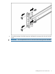
4. Line up the mounting rail with the cage nuts, and fasten the mounting rail to the rack with M5 screws. IMPORTANT: You must provide the screws to secure the slide mounting bracket assemblies.
NOTE: 5. 8 Apply some pressure when fastening the screws to the mounting rail. Repeat steps 1–4 for the other mounting rail.
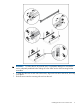
WARNING! To reduce the risk of personal injury or equipment damage, be sure that the rack is adequately stabilized before sliding the inner slides into the slide mounting bracket assemblies. 6. 7. To install the side rails on each side of the server, align each side rail to the server, and snap it into place. Slide the server onto the mounting rails and into the rack.
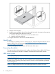
8. 9. Snap the server into place. Using the screws included in the rack kit as described in the rack kit instructions for preparing a server for shipment, fasten the server to the rack. a. Pull down the plastic retention lever on each side of the server. b. Insert the screws into each side. 10. Using the instructions in the rack kit, install the cable arm.
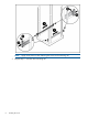
1. 2. 3. 4. Using the D-Shell Connector, connect the DC power cable to the first supply. Hand-tighten the thumb screws at the top and bottom of the shell. Securely connect the wire labeled Ground to an appropriate earth ground. Connect the other two wires to the appropriate outputs of a DC power source. CAUTION: If the product is connected to DC power sources that are not within the designated range of the power supplies, damage might occur. 5. Repeat steps 1–4 with the second DC power cable and supply.
DC input power The server can receive DC input from two different DC power sources. The power receptacles are located at the rear of the server. A maximum of two power supplies can be installed in the server. Installing two power supplies in the server provides 1+1 redundancy. Therefore, if one power supply fails, enough power is supplied to the server to operate. Trestore 1+1 functionality, you must promptly replace the failed power supply. A minimum of one power supply is required to power the server.
Figure 1 Rear panel components 1 2 3 4 5 6 7 8 PCI 5 PCI 6 PCI 4 PCI 2 PCI 3 PCI 1 Power supply 2 Power supply 2 LED 9 10 11 12 13 14 15 16 Power supply 2 power connector Power supply 1 Power supply 1 LED Power supply 1 power connector UID LED button USB connectors (2) Video connector NIC 1 connector 17 18 19 20 21 22 23 24 NIC 2 connector iLO 3 physical presence pinhole button Serial connector iLO 3 connector NIC 3 connector NIC 4 connector NIC link LED NIC activity LED Applying standby power to the
Safety information To prevent injury and equipment damage when performing removal and replacement procedures, follow all instructions carefully. Voltage might be present within the server. Many assemblies are sensitive to damage by ESD.
Table 3 Setup checklist Step Action Procedure Status Standard setup 1 Preparation 1. Determine an access method to select and connect the cables. 2. Determine a LAN configuration method and assign an IP address if necessary.
6. Start the operating system. For more information, see the operating system documentation. Powering on the server manually NOTE: If the power restore feature is set to Always On through the iLO 3 MP PR command, the server automatically powers on to the full power state when the power cord is plugged in to the server. 1. 2. 3. Plug all power cables into the receptacles on the rear panel of the server. To start the server, press the power button. Start the operating system.
2. After memory test and CPU late self test, the following message appears: Press Ctrl-C now to bypass loading option ROM UEFI drivers. The prompt times out if Ctrl-C is not pressed within a few seconds. If Ctrl-C is pressed, you are presented with two options: • Bypass loading from I/O slots. • Bypass loading from I/O slots and core I/O. The Bypass loading from I/O slots and core I/O option may be useful if a bad core I/O UEFI driver is preventing system boot.
To view boot options, or launch a specific boot option, press B to launch the Boot Manager. To configure specific devices, press D to launch the Device Manager. This is an advanced feature and must only be performed when directed.
To perform maintenance on the system such as adding, deleting, or reordering boot options, press M to launch the Boot Maintenance Manager. To perform more advanced operations, press S to launch the UEFI Shell. To view the iLO LAN configuration, press I to launch the iLO Setup Tool. Saving UEFI configuration settings You can configure other UEFI settings at this time. For more UEFI configuration options, see the Utilities appendix in the HP Carrier-Grade rx2800 i2 Server DC Solution User Service Guide.
Installing the latest firmware using HP Smart Update Manager The HP Smart Update Manager utility enables you to deploy firmware components from either an easy-to-use interface or a command line. It has an integrated hardware discovery engine that discovers the installed hardware and the current versions of firmware in use on target servers. This prevents extraneous network traffic by only sending the required components to the target.
2 Support and other resources Contacting HP Information to collect before you contact HP NOTE: HP recommends that you record any changes that you make to your system, as well as how the changes affect system behavior. 1. 2. 3.
HP contact information For the name of the nearest HP authorized reseller: • See the Contact HP worldwide (in English) webpage (http://www8.hp.com/us/en/ hp-information/summary/ww-contact-us.html). For HP technical support: • • In the United States, for contact options see the Contact HP United States webpage (http:// www8.hp.com/us/en/contact-hp/contact.html). To contact HP by phone: ◦ Call 1-800-HP-INVENT (1-800-474-6836). This service is available 24 hours a day, 7 days a week.
sent to your authorized HP Channel Partner for on-site service, if configured and available in your country. The software is available in two variants: • HP Insight Remote Support Standard: This software supports server and storage devices and is optimized for environments with 1-50 servers. Ideal for customers who can benefit from proactive notification, but do not need proactive service delivery and integration with a management platform.
KeyCap The name of a keyboard key or graphical interface item (such as buttons, tabs, and menu items). Note that Return and Enter both refer to the same key. Emphasis Text that is emphasized. Bold Text that is strongly emphasized. Bold The defined use of an important word or phrase. ComputerOut Text displayed by the computer. UserInput Commands and other text that you type. Command A command name or qualified command phrase. Option An available option.
Standard terms, abbreviations and acronyms ACPI Advanced Configuration and Power Interface. DDNS Dynamic DNS. DHCP Dynamic Host Configuration Protocol. ESD Electrostatic discharge. FRU Field Replaceable Unit. HDD Hard disk drive. iLO 3 Integrated Lights Out 3. MAC Media Access Control. NEBS Network Equipment Building Systems PAL Processor Abstraction Layer. SAL System Abstraction Layer. SEL System event log. SFF Small form factor. SID System Insight Display.
Index Symbols NVRAM configuration utility, 19 1+1 capability power supplies, 12 O A P AC power input, 12 PC command, 15, 16 power full state, overview, 15 off state, overview, 15 PR command, 15 sources, 12 standby, 13 standby state, overview, 15 states, 12, 15 power reset command see PR command powering off the server, 16 manually, 16 using the iLO 3 MP PC command, 16 powering on the server, 15–16 manually, 16 using the iLO 3 MP PC command, 15 PR command, 15 C checklist console, 14 iLO 3 setup, 14 s