HP Carrier-Grade rx2800 i2 Server DC Solution User Service Guide Abstract This document contains specific information that is intended for users of this HP product.
© Copyright 2011, 2012 Hewlett-Packard Development Company, L. P. Legal notices The information contained herein is subject to change without notice. The only warranties for HP products and services are set forth in the express warranty statements accompanying such products and services. Nothing herein should be construed as constituting an additional warranty. HP shall not be liable for technical or editorial errors or omissions contained herein.
Contents 1 Overview..................................................................................................8 Server subsystems.....................................................................................................................9 Internal components.............................................................................................................9 I/O subsystem..................................................................................................................
Operating system is loaded onto the server...........................................................................30 Operating system is not loaded onto the server......................................................................30 OS login prompt................................................................................................................30 Installing the latest firmware using HP Smart Update Manager.....................................................
Basic and advanced troubleshooting tables...........................................................................61 Troubleshooting tools..............................................................................................................64 LEDs ................................................................................................................................65 Front panel................................................................................................................
I/O subsystem behaviors....................................................................................................85 Customer messaging policy.................................................................................................85 Troubleshooting the iLO 3 subsystem.........................................................................................87 iLO 3 MP LAN LED on the rear panel...................................................................................
HP Support Center......................................................................................................125 Subscription service..........................................................................................................125 HP Insight Remote Support Software........................................................................................125 New and changed information in this edition...........................................................................
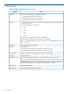
1 Overview Table 2 Hardware specifications for the server Component Processors Server One or two Itanium Dual-Core or Quad-Core processors: • 1.6-GHz Dual-Core processor 10-MB cache • 1.46-GHz Quad-Core processor 16-MB cache • 1.
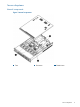
Server subsystems Internal components Figure 1 Internal components 1 Fans 2 Processors 3 DIMM risers Server subsystems 9
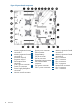
Figure 2 System board components 1 2 3 4 5 6 7 8 9 10 Overview Memory expansion board connector 1 Memory expansion board connector 2 Processor socket 0 Processor socket 1 SATA optical drive connector CPU 0 power connector Front I/O connector Power supply backplane connector Intrusion switch connector 10 11 12 13 14 15 16 17 18 Primary riser connector TPM connector System battery SAS B connector SAS A connector Secondary riser connector SAS cache module connector SAS power connector CPU 1 power connect
Figure 3 Internal USB location I/O subsystem The I/O subsystem consists of the core I/O and two optional I/O riser boards. Wake-on-LAN is not enabled on any PCIe Public slots. The server does not support PCI Hot Plug (PHP). The standard I/O Riser supports one full-height, full-length PCIe x8 and two full-height, half-length PCIe x4 add-in cards. The second riser option supports one full-height, full-length PCIe x8, and one full-height, half-length PCIe x8 add-in cards.
NOTE: To use all 8 disks with the zero memory option, the following RAID configurations are supported: – RAID 0: 1 or 2 LUNs striped with up to 8 disks – RAID 10: 1 or 2 LUNs striped and mirrored with even number of up to 8 disks – RAID 1: 1 LUN using 2 mirrored disks, and one additional LUN in RAID 0 or 10 Example configurations of eight disks with zero memory • – LUN 1: RAID 1 bays 1 and 2 – LUN 2: RAID 0 bays 3, 4, 5, 6, and 7 – Hot Spare: bay 8 – LUN 1: RAID 10 bays 1, 2, 3, and 4 – LUN
4 Optical drive bay Storage and media devices The server supports up to eight hot-plug SAS HDDs and one optical (SATA DVD+RW) drive, with LEDs that indicate activity and device statuses. Figure 5 SAS device numbers Rear panel controls and ports The server rear panel includes communication ports, I/O ports, USB ports, DC power connectors, and the locator LED and button. LEDs located on the rear panel of the server signal the operational status of the rear panel components.
15 16 14 Overview Video connector NIC 1 connector 24 NIC activity LED
2 Site preparation For information on general computer room site preparation, see the HP Generalized Site Preparation Guide on the HP website at http://www.hp.com/go/Integrity_Servers-docs. IMPORTANT: To avoid hardware damage, allow the thermal mass of the product to equalize to the temperature and humidity of the installation facility after removing the shipping materials. A minimum of one hour per 10° C (50° F) of temperature difference between the shipping facility and installation facility is required.
Maximum Inrush Current duration (mS) Maximum British Thermal Unit Rating (Btu-Hr) NOTE: 1 1 3 4713 4610 4662 Battery return terminals are isolated DC returns (DC-I). If an overload triggers the power supply overload protection, the system is immediately powered off. To reset the power supply unit: 1. Disconnect the power cord. 2. To determine what caused the overload contact an HP support representative. 3. Reconnect the power cord. 4. Reboot the system.
Verifying the inventory The sales order packing slip lists all the equipment shipped from HP. Use this packing slip to verify that all equipment has arrived. NOTE: To identify each item by part number, see the sales order packing slip. Returning damaged equipment If the equipment is damaged, immediately contact your HP customer service representative. The service representative initiates appropriate action through the transport carrier or the factory and assists you in returning the equipment.
3 Installing the server This equipment is intended for installation in Network Telecommunication Facilities. CAUTION: Before starting this procedure, see “Preventing electrostatic discharge” (page 25). Installation sequence and checklist Step Description 1 Perform site preparation (see “Site preparation” (page 15)). 2 Install the server into the rack. 3 Connect cables to the server. Completed a. Connect the DC input power cables. b. Connect LAN core I/O cables. c. Connect the iLO 3 MP LAN cable.
Hardware kit contents In addition to the supplied items: • If needed, obtain the HP kit (AT112-2100A) for connecting to a rack that has round holes. (The kit includes eight round hole cage nuts and eight screws.) • The appropriate tool for the screws. Installing the rack mount kit CAUTION: Plan the rack installation so that the heaviest item is on the bottom of the rack. Install the heaviest item first, and then continue to populate the rack from the bottom to the top.
4. Line up the mounting rail with the cage nuts, and fasten the mounting rail to the rack with M5 screws. IMPORTANT: NOTE: 20 Installing the server You must provide the screws to secure the slide mounting bracket assemblies. Apply some pressure when fastening the screws to the mounting rail.
5. Repeat steps 1–4 for the other mounting rail. WARNING! To reduce the risk of personal injury or equipment damage, be sure that the rack is adequately stabilized before sliding the inner slides into the slide mounting bracket assemblies. 6. 7. To install the side rails on each side of the server, align each side rail to the server, and snap it into place. Slide the server onto the mounting rails and into the rack.
8. 9. Snap the server into place. Using the screws included in the rack kit as described in the rack kit instructions for preparing a server for shipment, fasten the server to the rack. a. Pull down the plastic retention lever on each side of the server. b. Insert the screws into each side. 10. Using the instructions in the rack kit, install the cable arm.
1. 2. 3. 4. Using the D-Shell Connector, connect the DC power cable to the first supply. Hand-tighten the thumb screws at the top and bottom of the shell. Securely connect the wire labeled Ground to an appropriate earth ground. Connect the other two wires to the appropriate outputs of a DC power source. CAUTION: If the product is connected to DC power sources that are not within the designated range of the power supplies, damage might occur. 5. Repeat steps 1–4 with the second DC power cable and supply.
DC input power The server can receive DC input from two different DC power sources. The power receptacles are located at the rear of the server. A maximum of two power supplies can be installed in the server. Installing two power supplies in the server provides 1+1 redundancy. Therefore, if one power supply fails, enough power is supplied to the server to operate. To restore 1+1 functionality, you must promptly replace the failed power supply. A minimum of one power supply is required to power the server.
Safety information To prevent injury and equipment damage when performing removal and replacement procedures, follow all instructions carefully. Voltage might be present within the server. Many assemblies are sensitive to damage by ESD.
Table 5 Setup checklist Step Action Procedure Status Standard setup 1 Preparation 1. Determine an access method to select and connect the cables. 2. Determine a LAN configuration method and assign an IP address if necessary.
6. Start the operating system. For more information, see the operating system documentation. Powering on the server manually NOTE: If the power restore feature is set to Always On through the iLO 3 MP PR command, the server automatically powers on to the full power state when the power cord is plugged in to the server. 1. 2. 3. Plug all power cables into the receptacles on the rear panel of the server. To start the server, press the power button. Start the operating system.
2. After memory test and CPU late self test, the following message appears: Press Ctrl-C now to bypass loading option ROM UEFI drivers. The prompt times out if Ctrl-C is not pressed within a few seconds. If Ctrl-C is pressed, you are presented with two options: • Bypass loading from I/O slots. • Bypass loading from I/O slots and core I/O. The Bypass loading from I/O slots and core I/O option may be useful if a bad core I/O UEFI driver is preventing system boot.
To view boot options, or launch a specific boot option, press B to launch the Boot Manager. To configure specific devices, press D to launch the Device Manager. This is an advanced feature and must only be performed when directed.
To perform maintenance on the system such as adding, deleting, or reordering boot options, press M to launch the Boot Maintenance Manager. To perform more advanced operations, press S to launch the UEFI Shell. To view the iLO LAN configuration, press I to launch the iLO Setup Tool. Saving UEFI configuration settings You can configure other UEFI settings at this time. For more UEFI configuration options, see Appendix A (page 130).
Installing the latest firmware using HP Smart Update Manager The HP Smart Update Manager utility enables you to deploy firmware components from either an easy-to-use interface or a command line. It has an integrated hardware discovery engine that discovers the installed hardware and the current versions of firmware in use on target servers. This prevents extraneous network traffic by only sending the required components to the target.
4 Operating system procedures Operating systems supported on the server • HP-UX 11i v3 HWE 1009 or later • HP OpenVMS v8.4 with VMS84I_UPDATE-V0500, rx2800 i2 enablement kit NOTE: Wake-On-LAN (WOL) is supported with Integrity rx2800 i2 Servers running HP-UX 11i v3. WOL is not supported with Integrity servers running OpenVMS environments. The supported remote power-on solution for OpenVMS environments is iLO 3.
4. Locate the device you want to boot from. a. For DVD, locate the device: i. To list all device names from the UEFI Shell prompt, use the map command. ii. From the list generated by the map command, locate the device name (in this example, fs6). fs2:\> map Device mapping table fs6 :Removable CDRom - Alias cd66d0a blk6 PcieRoot(0x30304352)/Pci(0x1D,0x7)/USB(0x3,0x0)/CDROM(0x0) NOTE: Your DVD drive might not be named fs6. Make sure you verify the ID appropriate to your DVD device. iii.
Installing HP OpenVMS with Infoserver Utility Infoserver Utility enables OpenVMS installations and upgrades over the network. To install the OS using Infoserver, see the "Setting Up and Performing Network Booting" section in HP OpenVMS Version 8.4 Upgrade and Installation Manual on the HP website http://h71000.www7.hp.com/ doc/84final/ba322_90087/ba322_90087.
Booting and shutting down HP-UX • To add an HP-UX entry to the boot options list, see “Adding HP-UX to the boot options list” (page 35). • To boot HP-UX, use one of the following procedures: • ◦ To boot HP-UX in the standard mode, see “HP-UX standard boot” (page 36). HP-UX boots in multi-user mode. ◦ To boot HP-UX in single-user mode, see “Booting HP-UX in single-user mode” (page 37). ◦ To boot HP-UX in LVM-maintenance mode, see “Booting HP-UX in LVM-maintenance mode” (page 37).
• bcfg boot mv #a #b–Move the item number specified by #a to the position specified by #b in the boot options list. • bcfg boot add # file.EFI "Description"–Add a new boot option to the position in the boot options list specified by #. The new boot option references file.EFI and is listed with the title specified by Description. For example, bcfg boot add 1 \EFI\HPUX\HPUX.EFI "HP-UX 11i v3" adds an HP-UX 11i v3 item as the first. For details, see the help bcfg command. 4.
6. Allow the HPUX.EFI loader to proceed with the boot command specified in the AUTO file, or manually specify the boot command. By default, the HPUX.EFI loader boots using the loader commands found in the \EFI\HPUX\AUTO file on the UEFI System Partition of the selected boot device. The AUTO file typically contains the boot vmunix command. To interact with the HPUX.EFI loader, interrupt the boot process (for example, type a space) within the time-out period provided by the loader.
NOTE: 1. Commands are not case-sensitive. Access the UEFI Shell environment. a. Log in to iLO for Integrity, and then to access the system console, enter CO. When accessing the console, confirm that you are at the UEFI Front Page. If you are at another UEFI menu, then choose the Exit option or press X to exit the menu. Exit until you return to the screen that lists the keys that can be pressed to launch various Managers. b. 2. To launch the UEFI shell, press S.
5. At the EFI Boot Manager menu, choose an item from the boot options list. Each item in the boot options list refers to a specific boot device and provides a specific set of boot options or arguments to use when booting the device. 6. 7. 8. To initiate booting using the chosen boot option, press Enter. Exit the console and iLO MP interfaces. Press Ctrl–B to exit the system console and return to the MP Main Menu. To exit the MP Main Menu, press X.
2. At the OpenVMS DCL prompt, enter the @SYS$SYSTEM:SHUTDOWN command, and then specify the shutdown options in response to the prompts given. NOTE: Use the command in step 2 when you shut down OpenVMS for the first time. If you have shut down OpenVMS more than once, use the $ shutdown command.
5 Optional components This section describes how to install components into the server that are not factory-installed. If you have additional components to install, be sure to install the additional components before installing the server into your rack configuration. Most servers are pre-configured with all components installed before shipping from the HP factory.
2. To install the hard drive, push in the drive and then close the locking lever. Installing a hot-swappable power supply The server has two hot-swappable power supplies. This power supplies are located at the rear of the server. CAUTION: Observe all ESD safety precautions before attempting this procedure. Failure to follow ESD safety precautions might result in damage to the server. NOTE: The power supply is a hot-swappable device.
2. Install the power supply. Removing the access panel 1. 2. Use the T-15 Torx screwdriver attached to the rear of the server to loosen the security screw on the hood latch. Lift the hood latch handle, and then remove the access panel. To replace the component, reverse the removal procedure. Removing the PCI riser cage CAUTION: For proper cooling, do not operate the server without the access panel, baffles, expansion slot covers, or blanks installed.
2. Remove the PCI riser cage. To replace the component, reverse the removal procedure. When replacing the PCI riser cage, to ensure that it has properly seated into the system board, push down on the top of the component where the riser is located. Removing expansion slot covers CAUTION: To prevent damage to the server or expansion boards, power off the server, and then remove all DC power cords before removing or installing the PCI riser cage.
3. Remove the expansion slot cover. • To remove slot cover 1 or 4, push the retainer to release it, and then slide out the cover. • To remove slot covers 2 and 3, lift up and remove the latch, and then remove the cover. • To remove slot covers 5 and 6, push down on the latch, rotate the latch down, and then remove the cover. Installing expansion boards The server supports up to two PCIe riser boards. Each PCIe riser board holds up to three PCIe cards.
2. 3. 4. Remove the PCI riser cage. See “Removing the PCI riser cage” (page 43). Remove the expansion slot cover. See “Removing expansion slot covers” (page 44). Install the expansion board. 5. 6. 7. Connect any required internal cables to the expansion board. Reinsert the PCI riser cage into the chassis. Connect any required external cables to the expansion board. Installing a full-length expansion board 46 1. 2. 3. 4. Remove the access panel. See “Removing the access panel” (page 43).
Installing DIMMs Memory configurations The server has 24 system memory DIMM slots located on 4 memory expansion boards (6 DIMMs per expansion board). You can access the memory expansion boards without removing the airflow guide or the I/O card cage. The DIMMs are partitioned by the number of processors installed in the server. If you have only one processor installed in the system, you can only use 12 of the 24 memory slots. CAUTION: Observe all ESD safety precautions before attempting this procedure.
Table 6 Memory Load Order (continued) 2 Processor system (socket 0 and 1) 1 Processor system (socket 0) Pair number Expansion board Memory slots Expansion board Memory slots 11 Expansion board 2 2C and 5C — — 12 Expansion board 4 2C and 5C — — TIP: You can load DIMM pairs on a single expansion board at a time, but this option reduces system performance. Supported DIMM sizes DIMMs seat onto the four memory expansion boards that seat on the system board.
◦ Do not mix unbuffered DIMMs with registered DIMMs. ◦ A maximum of two unbuffered DIMMs per channel can be installed. ◦ If quad-rank DIMMs are installed for a processor, a maximum of two DIMMs can be installed on each channel for that processor. ◦ If a channel contains quad-rank DIMMs, the quad-rank DIMM must be installed first on the channel. Installing DIMMs 1. 2. Remove the access panel. See “Removing the access panel” (page 43). Lift the memory expansion board handle and remove the component.
4. Replace the memory expansion board. CAUTION: Be sure to align the three stand-offs in the alignment slots. TIP: If you see abnormal error lights after installing DIMMs, try uninstalling and reinstalling the DIMMs and the memory expansion board to make sure the DIMMs and memory expansion board are correctly seated. Installing a processor The server can use dual-core or quad-core processors. Dual-core processors contain two cores that function as separate processors.
Processor load order The server holds up to two dual-core or quad-core processors on the system board. The sockets on the system board are labeled Module 0 and Module 1. If the server has only one processor, it is installed in socket 0. Install the second processor in socket 1. See Figure 2 (page 10) for the processor socket numbers.
3. Transfer the duplicate part/serial numbers label from the processor module to the processor heat sink: a. Remove the duplicate tear-away label that lists the part and serial numbers from the processor module. b. Place the label on the top of the heat sink. 4. Install the processor over the load posts. NOTE: Ensure pin 1, indicated on the empty socket with an embossed triangle, matches the pin 1 marker on the processor module, the chamfered corner of its attached voltage regulator heat sink. 5.
CAUTION: To avoid damage to the server and processor, ensure the processor heat sink locking handle is fully back against the stops, rotated approximately 120° back. Also, verify that the plastic tabs on the processor heat sink are fully pulled out before installation. 6. Install the heat sink over the load posts. CAUTION: into place.
CAUTION: To prevent thermal instability and damage to the server, do not separate the processor module from the processor heat sink after they have been coupled. NOTE: Positive engagement clicking must occur during engaging of the processor heat sink and processor module onto the socket to ensure proper seating.
7. Secure the heat sink to the processor. a. Slide both plastic locking tabs into place. See callout 1 in the following figure. b. Flip the latch down. See callout 2 in the following figure. WARNING! The heat sink locking lever can constitute a pinch hazard. Keep your hands on top of the lever during installation to avoid personal injury. CAUTION: To prevent thermal instability and damage to the server, do not separate the processor module from the processor heat sink after they have been coupled. 8.
9. Tie wrap the processor cable to the right tie point on the processor assembly. CAUTION: When the processor is installed, dress all slack in the power cable to the connector end of the cable. Failure to do so can result in pinched or damaged processor power cables. NOTE: If you are adding an additional processor to your server, the DIMMs in the server must be reconfigured to support both processors. For more information, see “Memory configurations” (page 47).
3. Enter info all from the UEFI Shell prompt. The following appears: NOTE: Your display might not match the display shown.
Boottest: BOOTTEST Settings Default Variable OS is not speedy boot aware.
6 Troubleshooting The purpose of this chapter is to provide a preferred methodology (strategies and procedures) and tools for troubleshooting the server error and fault conditions. How to contact HP For information on how to contact HP, see “Contacting HP” (page 124).
You might have to perform specific recovery procedures to finish the repair. For example, if the system board is replaced, you need to restore customer specific information. Should a failure occur, the System Insight Display LEDs, SEL and FPL help you identify the issue or CRU: • LEDs. The front panel LEDs and LAN LEDs of the server change color and blink to help identify specific issues. • The System Event Log (SEL) provides detailed information about the errors identified by the LEDs.
Table 8 Troubleshooting entry points (continued) Entry point Subsection or location Offline and Online Diagnostics/INIT button “Troubleshooting tools” (page 64) System Event Analyzer “Troubleshooting tools” (page 64). For more information about this tool, see http://www.compaq.com/support/svctools/webes/. Basic and advanced troubleshooting tables The following troubleshooting tables are designed for use by both trained and untrained support personnel.
Table 9 Basic low end troubleshooting (continued) Step Condition Action is flashing amber, and power is steady green). Examine each power supply LED. If not solid green, replace power supply (for details, see “Troubleshooting the power subsystem ” (page 83)). The issue is fixed when the failure condition is corrected, and the front panel LED states are as follows: system health is steady green, and power is steady green. 3 System health LED is flashing red.
Table 9 Basic low end troubleshooting (continued) Step Condition Action 3. Look for loose, damaged, or disconnected power and signal cables on the I/O riser. The issue is fixed when iLO 3 MP menu appears on the system console, and the system health is steady green. 4b Cannot see UEFI prompt on system console. Nothing might be logged for this condition (system health is steady green, and power is steady green). 1. Examine the SID LEDs for any faults. 2.
Table 10 Advanced low end troubleshooting Step Symptom/Condition Action 6 Cannot read System Event Log from the iLO console. System event logging has stopped and a iLO MP malfunction is assumed (system health is steady green, and power is steady green). 1. Examine console messages for any UEFI errors or warnings about iLO operation or communications. 2.
LEDs Front panel Figure 9 Front panel LEDs and buttons 1 UID LED and button 2 System health LED 3 Power button Table 11 Front panel controls Name Function Status UID button This button helps locate a particular server within a rack of servers. You can remotely activate this function through various system utilities.
There are a total of three LEDs, arranged vertically, with the UID button and the power button each having an integrated LED. In addition to the two integrated button/LEDs, there is a health LED. System health LED The front panel health LED indicates the status of the components that are externally serviceable. Whenever the system health LED illuminates, the corresponding CRU illuminates for the failed component.
Figure 10 System Insight Display LEDs Table 14 SID LED states LED State NICs • Off = No link to network • Flashing green = Network link and activity • Green = Network link Power Capping Over Temp NOTE: This LED is not used. Power capping operation can be observed through iLO 3. For more information, see the HP Integrity iLO 3 Operations Guide.
Table 15 SID LED States Definition Flash Rate LED Color CRU health is assumed good. LED Off Off CRU health last known to be bad. Steady Amber NOTE: The Power Supply LED illuminates only when a failure or fault is detected in a power supply. Loss of DC power to a power supply will generate a SEL entry, but does not result in the Power Supply LED illuminating.
Drive status LED The drive status LED can appear amber or blue. • Amber indicates a warning, or failure condition. • Blue is a locator LED that identifies a particular disk drive. Various software utilities, such as online diagnostics or SAS disk drive configuration tools, can activate the locator LED.
Optical drive The server has one SATA DVD+RW drive. This device has one activity LED.
Table 19 Rear panel LEDs and buttons Name Status Power supply LED • Green = Normal • Off = System is off or power supply has failed UID LED/button • Blue = Identification • Flashing blue = Remote iLO session or a firmware flash update is in progress • Off = Off NIC/iLO 3 activity LED • Green = Network activity • Flashing green = Network activity • Off = No network activity NIC/iLO 3 link LED • Green = Network link • Off = No network link iLO 3 physical presence The iLO 3 physical presence button e
If the operating system cannot be booted, then use the offline support tools to help resolve the issue. The offline support tools are available either from the UEFI partition, or from the IPF Offline Diagnostics and Utilities CD (IPF systems only). After the issue preventing booting has been resolved, boot the operating system, and then use the online support tools for any further testing.
Table 21 Online Support Tools List (continued) Functional Area Information Verify Exercise Diagnose Expert Disk/Arrays Yes Yes Yes No No Tape Yes Yes Yes Yes Yes M/O Yes No No No Yes Add-On Network I/O Yes Cards Yes Yes No Yes Add-On Mass Storage Yes I/O Cards No No No No Offline support tools list Table 22 Offline Support Tools List Offline Tool Functional Area CPUDIAG Processor Diagnostic MEMDIAG Memory Diagnostic MAPPER System Mapping Utility TITANDIAG SBA/LBA C
using hardware event monitoring, users can virtually eliminate undetected hardware failures that could interrupt system operation or cause data loss.
• The iLO 3 MP can display event logs: SEL events are sent over the IPMB. • Event logs can also be read back over the PDH bus by software (for example, the IPMI driver or agent) for storage on disk. Using event logs To consult the event logs: 1. Connect to the system console. 2. Use Ctrl-B to access the iLO 3 MP menu. 3.
System build-up troubleshooting procedure Use into 1. 2. 3. this procedure only when the system powers on and remain powered on but does not enter or pass power-on self test (POST) or does not boot to the UEFI menu. Remove the AC power cord from each power supply and extend the server, if racked. Remove all of the SAS disk drives from the front of the server. Remove the top cover to gain access to, and remove all CRUs, except the system board. NOTE: 4.
8. Check the SEL for any memory-related IPMI alerts. NOTE: Your display might not exactly match the display shown. Log Entry 1: 01 Aug 2012 17:20:38 Alert Level 5: Critical Keyword: INSUFFICIENT_SYSTEM_MEMORY This HW configuration does not have enough memory for the OS to boot.
Troubleshooting is based on observation of server status indications and error messages, and by reviewing system event logs. You can observe the LED indicators on the front and rear of the server. Error messages appear on local and remote consoles. System history (console, event, and history logs) is available through the iLO 3 MP, and is accessed through the console. Additional information about troubleshooting is available on the CD provided with the server.
UEFI menu is not available If you cannot access the UEFI from either the main disk partition or the CD, use the following tools to resolve the issue: • Front panel LEDs • iLO 3 MP ◦ Console messages ◦ SEL ◦ FPL Operating system does not boot If the operating system does not boot, boot to UEFI, and use the following tools to view the system logs. Analyze any error messages to resolve the issue.
1. 2. 3. 4. 5. Remove and reinsert the faulty hard drive. Swap the hard drive with one from another slot or with a known good spare. Remove and reinstall the hard drive backplane. Verify that connectors are fully engaged. Replace the hard drive backplane. Re-seat cables. Console issues Console issues during installations can be caused by faulty interconnections. If you are experiencing monitor, keyboard, or mouse issues: 1. View the monitor controls. Adjust contrast and brightness as required. 2.
are reported for CMC events when thresholds are exceeded for single-bit errors; fatal processor errors cause global / local MCA events.
Table 27 Processor events that might illuminate SID LEDs (continued) Diagnostic LEDs Sample IPMI Events Cause Processor Type E0h, 745d:26d A watchdog SFW timer expired and determined that a monarch processor is not responding.
0 of side 0. All other causes of memory DIMM errors are corrected by the processor and reported to the PDT / SID LED panel. Customer messaging policy • The diagnostic LED illuminates only for memory DIMM errors when isolated to a specific DIMM. If there is uncertainty about a specific DIMM, then the customer is pointed to the SEL for any actions, and the DIMM CRU LED for the suspect DIMM on the System Insight Display is not lit.
Power subsystem behavior For the server, each bulk power supply CRU provides 800 watts of DC power from a nominal 120 VAC, 50-60 Hz; and 1200 watts from a nominal 240 VAC, 50-60 Hz. The iLO MP chip located on the system board controls the flow of +12 V DC power to the server CRUs. You can control and display power supply status remotely with the iLO 3 MP pc and ps commands, respectively. The typical power-on sequence of the server is as follows: 1.
for the fan cooling zone it controls. Each dual fan assembly CRU is identified by the server as fans 1 through 6 both for logging purposes and for fault identification on the diagnostic LED panel.
Table 32 I/O subsystem events that light SID LEDs Diagnostic LEDs Sample IPMI events Cause Source Notes I/O Card Type 02h, 03h:05h:01h Over-current on PCI slot iLO MP Likely a short on I/O card or I/O slot.
Table 33 I/O card events that might illuminate SID LEDs (continued) Diagnostic LEDs Sample IPMI Events Cause Source I/O Card Type E0h, 144d:26d SFW IO_SBA_CLEAR_ERR_FAILED I/O SBA clear error failed Type E0h, 146d:26d PCI-X slot power on error SFW I/O Card Notes IO_SLOT_POWER_ON_ERROR I/O Card Type E0h, 145d:26d PCI-X slot has incorrect default power state SFW I/O host bridge (Lower Bus Adapter) is inaccessible because rope reset failed to complete SFW PCI clock DLL error SFW I/O rope r
NOTE: On the server, only the activity LED is used. The status LED is not monitored by the OS. Verify that the LED shows the correct activity indication for all disk drives that you installed: 1. Turn on power to the server and display monitor. 2. During the boot sequence, watch the activity LED on each SAS disk drive. The LED quickly cycles from amber to green. The LED stays steady green until the drive spins up. 3.
NOTE: In the standard boot process, shown in Table 36 (page 88), even though the iLO MP is running while the system is shut down (power LED is steady amber), it does not drive the system health LED to steady green until +12 V DC power from the Bulk Power Supplies is applied. The following list itemizes the steps that characterize basic platform boot flow. Step numbers provided correspond to the steps in Table 36 (page 88). 3.
Firmware issues are relatively rare, and, therefore, you must determine other causes before considering a firmware issue. If you are attempting to resolve a firmware issue, the possible failure areas are as follows: • Unsupported firmware installation • Corrupt firmware installation To troubleshoot firmware issues: 1. Verify that all system and iLO firmware components are from the same release (use the iLO 3 sr command). 2. Reinstall all firmware.
7 Removal and replacement procedures IMPORTANT: Replacing the fans and power supplies If a cooling fan or power supply fails, you must replace it. Replacement usually takes no longer than 5 minutes. For instructions on replacing these components, see “Removing and replacing a hot-swap fan” (page 101) and “Removing and replacing a hot-swap power supply” (page 98).
Table 37 CRU list (continued) Description Spare part number PCA System board AH395-69001 PCA, Diagnostic and Front IO Board AH395-69003 SAS Disk Backplane 507690-001 Power Supply Backplane 496062-001 Fans Replacement, Fan Module Assembly AH395-67003 Cables Replacement Intrusion Switch and Cable150mm AH395-67002 SATA optical drive power/signal combo cable 496071-001 Cache super capacitor and cable 587324-001 Mini SAS connector and cable x2 498425-001 I/O PCA, PCIe 2D FireMV2250 Graphics (
Required tools • T-10/T-15 wrench (attached to the outside of the server) Safety considerations Before performing service procedures, review all the safety and electrostatic discharge information. • For information on general safety procedures, see “Safety information” (page 25). • For information on electrostatic discharge prevention, see “Preventing electrostatic discharge” (page 25).
2. Extend the server from the rack. WARNING! To reduce the risk of personal injury or equipment damage, be sure that the rack is adequately stabilized before extending a component from the rack. 3. After performing the installation or maintenance procedure, slide the server back into the rack, and then press the server firmly into the rack to secure it in place. WARNING! To reduce the risk of personal injury, be careful when pressing the server rail-release latches and sliding the server into the rack.
NOTE: 1. 2. If installing a hot-plug device, you do not have to power off the server. Back up the server data. Shut down the operating system as directed by the operating system documentation. NOTE: If the operating system automatically places the server in Standby mode, omit the next step. 3. Press the Power On/Standby button to place the server in Standby mode. When the server activates Standby power mode, the system power LED changes to amber.
2. Open the cable management arm. Cable management arm with right-hand swing NOTE: To access some components, you might have to remove the cable management arm. To access the product rear panel components, open the cable management arm: 1. Power off the server (“Powering off the server” (page 94)). 2. Swing open the cable management arm. 3. Remove the cables from the cable trough. 4. Remove the cable management arm.
Remove the component as indicated. Figure 13 Hard drive filler removal To replace the blank, slide the blank into the bay until it locks into place. Removing and replacing a hot-plug SAS hard drive The server supports up to eight SFF, 2.5-inch SAS hard drives. Each drive is equipped with two LEDs that indicate activity and device status. To remove the component: CAUTION: For proper cooling do not operate the server without the access panel, baffles, expansion slot covers, or blanks installed.
Figure 14 Removing the blank To replace the component, reverse the removal procedure. Removing and replacing a hot-swap power supply The server supports 1+1 redundant power supply when two power supplies are installed and no redundancy when only one power supply is installed. NOTE: Power redundancy is dependent on the number of power supplies, processors, and DIMMs in a system. Additional components, such as HDDs or PCIe cards, do not impact power redundancy. The server also supports power capping.
3. Remove the hot-swap power supplies. WARNING! To reduce the risk of electric shock or damage to the equipment, do not connect the power cord to the power supply until the power supply is installed. To replace the component, see “Installing a hot-swappable power supply” (page 42). Removing and replacing the access panel To remove the access panel see “Removing the access panel” (page 43). To replace the component, reverse the removal procedure.
4. 5. Remove the fans 2 and 3. See “Removing and replacing a hot-swap fan” (page 101). Disconnect the drive cable. 6. Lift the DVD release tab, and push out the drive. Then pull the drive straight out to remove it from the server. To replace the component, reverse the removal procedure. The optical drive cable routes beneath fan 2.
Removing and replacing a hot-swap fan Six fans cool the server. The fans are all redundant, hot-swappable, and interchangeable. If one fan unit fails, then the other fans increase speed to compensate. The fan units are N+1 redundant, meaning that the server has six fan units, but can operate with five fan units running. CAUTION: If more than one fan is removed or fails, the system does not shut down. If the temperature sensors detect conditions outside of operating limits, the system shuts down.
3. Remove the fan. CAUTION: Do not operate the server for long periods with the access panel open or removed. Operating the server in this manner results in improper airflow and improper cooling that can lead to thermal damage. To replace the component, reverse the removal procedure. Removing and replacing the power supply backplane 1. 2. 3. 4. 5. 6. 7. Power off the server (“Powering off the server” (page 94)). Remove all power supplies (“Removing and replacing a hot-swap power supply” (page 98)).
To replace the component, reverse the removal procedure. Removing and replacing the hard drive backplane 1. 2. 5. Power off the server (“Powering off the server” (page 94)). Extend or remove the server from the rack (“Removing the server from the rack” (page 95)) or “Extending the server from the rack” (page 93)). Remove the access panel (“Removing the access panel” (page 43)). Remove all hot-plug hard drives (“Removing and replacing a hot-plug SAS hard drive” (page 97)).
To replace the component, reverse the removal procedure. CAUTION: Carefully align the backplane center through-holes with the chassis mounting posts or you might damage components on the backplane. Removing and replacing the PCI riser cage To remove the component, see “Removing the PCI riser cage” (page 43). To replace the component, reverse the removal procedure. Removing and replacing expansion slot covers To remove the component see “Removing expansion slot covers” (page 44).
Removing and replacing a half-length expansion board 1. 2. 3. 4. 5. 6. 7. Power off the server (“Powering off the server” (page 94)). Extend the server from the rack (“Extending the server from the rack” (page 93)). Remove the access panel (“Removing and replacing the access panel” (page 99)). Disconnect any external cables that are connected to the expansion board. Remove the PCI riser cage (“Removing and replacing the PCI riser cage” (page 104)).
7. Remove the expansion board. To replace the component, see “Installing expansion boards” (page 45). Removing and replacing the cache module NOTE: The cache module is required to enable the full feature firmware stack for RAID support, and certain levels of RAID support also require the super capacitor module and a Advanced Pack license key. To enable Advanced Pack licensing, see “Adding a RAID Advanced Pack license key” (page 133). 1. 2. 3. 4. 5.
6. Remove the cache module. To replace the component, reverse the removal procedure. CAUTION: To prevent damage to the cache module during installation, be sure the cache module is fully inserted before pressing down. Removing and replacing the super capacitor pack 1. 2. 3. 4. 5. Power off the server (“Powering off the server” (page 94)). Extend or remove the server from the rack (“Removing the server from the rack” (page 95)) or “Extending the server from the rack” (page 93)).
7. Remove the super capacitor pack. To replace the component, reverse the removal procedure. Removing and replacing the processor baffle CAUTION: To prevent damage to the server, never power on a server without a processor baffle or processor in each processor socket. The processor baffle is needed for proper system cooling CAUTION: Immediately install a processor baffle in an empty processor socket. To avoid damage to the socket pins, the socket must never be uncovered for more than 5 seconds.
4. Pull the processor baffle straight up and out. To replace the processor baffle: 1. Line the processor baffle up with 4 load posts on each corner of the socket. 2. Guide the processor baffle straight down into place.
Removing and replacing a processor and heat sink module The server processor subsystem supports one or two Dual-Core or Quad-Core Itanium processors. When two processors are installed, the speeds must be identical. WARNING! To reduce the risk of personal injury from hot surfaces, allow the drives and the internal system components to cool before touching them. CAUTION: To prevent possible server malfunction, do not mix processors of different speeds or cache sizes.
7. Lift the processor and heat sink off of the socket, pulling straight up. 8. If the processor is not being replaced, install a processor baffle (“Removing and replacing the processor baffle” (page 108)). CAUTION: To avoid damage to processor socket pins and ensure proper system cooling, install a processor baffle in an empty processor socket. To replace a processor that is not defective, reverse the removal procedure. The replacement processor module is shipped from HP without a heat sink.
Refer to “Installing a processor and heat sink module” (page 51) for more information on the installation procedure. WARNING! DO NOT SEPARATE THE HEATSINK FROM THE PROCESSOR MODULE. Damage to the assembly will occur! Only Factory-Repair is authorized to separate assembly. Return the assembly in the heatsink box using the processor's defective return label. When the processor/heatsink assembly is removed from the server: • Do NOT separate the heatsink from the processor.
• 8 GB • 16 GB For memory configurations see “Installing DIMMs” (page 47). 1. Power off the server (“Powering off the server” (page 94)). 2. Extend or remove the server from the rack (“Removing the server from the rack” (page 95) or “Extending the server from the rack” (page 93)). 3. Remove the access panel (“Removing the access panel” (page 43)). 4. Remove the memory riser. NOTE: You can access the memory riser boards without removing the airflow guides.
To replace the component, reverse the procedure. Ensure that you follow the memory loading order when you replace DIMMs. For memory configuration information, see “Memory configurations” (page 47). CAUTION: Before inserting the memory expansion board, the three stand-off posts on the expansion board must be aligned with the alignment slots on the system board. Failure to align the stand-off posts correctly might result in damage to the expansion board.
To replace the component, reverse the removal procedure. IMPORTANT: engaged. Ensure that the new battery is fully seated and that all locking tabs are correctly For more information about battery replacement or proper disposal, contact an authorized reseller or an authorized service provider. Removing and replacing the SID 1. 2. 3. 4. 5. 6. 7. 8. 9. Power off the server (“Powering off the server” (page 94)). Extend the server from the rack (“Extending the server from the rack” (page 93)).
If installing a replacement SID module: 1. Retain the SID bezel, the transparent light pipe, and the black rubber light pipe. 2. Install the transparent plastic light pipe onto the SID bezel. 116 3. Install the SID bezel onto the metal chassis, ensuring the four latches all lock. 4. Put the black rubber light pipe onto the plastic light pipe.
5. Install the SID board by securing it with the two screws. 6. Fasten the two hexagon screws on the front of SID bezel to the VGA port.
7. Install the component as described above. Removing and replacing the intrusion switch cable 118 The 1. 2. 3. 4. intrusion switch screws face CPU 0. Power off the server (“Powering off the server” (page 94)). Remove the access panel (“Removing and replacing the access panel” (page 99)). Remove the PCI riser cage (“Removing and replacing the PCI riser cage” (page 104)). Open the processor cage. 5. Using a screwdriver, remove the switch.
6. Unplug the mating connector. To replace the component, reverse the removal procedure. Removing and replacing the system board IMPORTANT: If your system board has a TPM installed, you must order a new TPM when you order a replacement system board. Before replacing the system board, you must first back up the current TPM settings. See the HP-UX operating system documentation for more information. The TPM is not a customer-installable component.
7. Remove the PCI riser cage (“Removing and replacing the PCI riser cage” (page 104)). CAUTION: To prevent damage to the server or expansion boards, power off the server and remove all DC power cords before removing or installing the PCI riser cage. 8. 9. Remove all DIMMs risers (“Removing and replacing DIMMs” (page 112)). Remove all processor heat sink modules (“Removing and replacing a processor and heat sink module” (page 110)).
15. Remove the power supply backplane (“Removing and replacing the power supply backplane” (page 102)). 16. Remove the rear retaining screw. 17. Loosen the two system board thumbscrews. 18. Remove the system board from the chassis by pushing it toward the front and then lifting it.
19. Remove the four screws on the power supply cage, and remove the power supply cage. To migrate the processor to the spare system board: 1. Take the iLO label off the system board information label and place it over the iLO information pull tab on the front panel. 2. Install the spare system board. 3. Remove the battery insulator strip from the system board battery. CAUTION: The pins on the processor socket are very fragile. Any damage to them may require replacing the system board. 4. 5.
4. Enter saupdate.efi get_mode 0:1:0:0 to verify the SAS mode is set to RAID. After you replace the system board, you must port over the server serial number, product number and UUID. Labels on the server indicates these numbers. 1. Log in to ILO 3 MP, by using SSH, for example. 2. Access the MP Main Menu. 3. Enter CM at the hpiLO-> prompt. 4. Enter sysset at the CM:hpiLO> prompt, and it will show the system information.
8 Support and other resources Contacting HP Information to collect before you contact HP NOTE: HP recommends that you record any changes that you make to your system, as well as how the changes affect system behavior. 1. 2. 3.
HP contact information For the name of the nearest HP authorized reseller: • See the Contact HP worldwide (in English) webpage (http://www8.hp.com/us/en/ hp-information/summary/ww-contact-us.html). For HP technical support: • • In the United States, for contact options see the Contact HP United States webpage (http:// www8.hp.com/us/en/contact-hp/contact.html). To contact HP by phone: ◦ Call 1-800-HP-INVENT (1-800-474-6836). This service is available 24 hours a day, 7 days a week.
sent to your authorized HP Channel Partner for on-site service, if configured and available in your country. The software is available in two variants: • HP Insight Remote Support Standard: This software supports server and storage devices and is optimized for environments with 1-50 servers. Ideal for customers who can benefit from proactive notification, but do not need proactive service delivery and integration with a management platform.
Typographic conventions This document uses the following conventions. WARNING! A warning lists requirements that you must meet to avoid personal injury. CAUTION: A caution provides information required to avoid losing data or avoid losing server functionality. NOTE: A note highlights useful information such as restrictions, recommendations, or important details about HP product features. Book Title The title of a book. On the web and on the Instant Information CD, it may be a hot link to the book itself.
Customer self repair This section details the customer self repair components, and the estimated repair time it takes to replace a component. If during the diagnosis period HP (or HP service providers or service partners) identifies that the repair can be accomplished by the use of a CRU part, HP will ship that part directly to you for replacement. There are three categories of CRU parts: Yes Parts for which customer self repair is mandatory.
Standard terms, abbreviations and acronyms ACPI Advanced Configuration and Power Interface. BBWC Battery Backed Write Cache. CMC Corrected machine check. Cold-swappable A component that requires the operating system be shut down and the server powered off before it can be removed. Cold-swappable components are signified with blue touch points. CPE Corrected platform error. CRU Customer Replaceable Unit. DDNS Dynamic DNS. DHCP Dynamic Host Configuration Protocol. DMA Direct memory access.
A Utilities SAS disk setup Using the saupdate command The saupdate command is used to query or change the mode of the Smart Array P410i and Smart Array P411 controllers to HBA or RAID. Querying or changing modes is not supported for other controllers. The newly added commands to saupdate are: • Get Mode • Set Mode Get mode This command displays the current mode of the controllers. Syntax saupdate get_mode can be any one of the following strings.
Set mode IMPORTANT: If you are using HBA mode, do not install any disk that has previously been a part of a RAID volume into the system. Set mode is used to change the mode of the controller. If the controller is already in the required mode the following message appears: The controller at seg:bus:dev:funcis already in HBA|RAID mode. Syntax saupdate set mode [-f] can be any one of the strings listed in Table 41 (page 130).
To change the mode of the controller use saupdate set_mode [-f]. NOTE: A system reset or a reconnect-r is required after changing from HBA to RAID mode. An alert message about the possible data loss is displayed when a mode change command is issued. A confirmation is required before the actual mode change is made. This ensures unintentional change of mode does not happen.
3. 4. 5. 6. 7. To select the Raid Configurations section and select the RAID type for the logical drive, press Tab. To select the Spare section and assign spare disks, as needed, press Tab. To create the logical drive, press Enter. A summary of your choices appears. To save the configuration, press F8. If the function keys are disabled, press Esc and then press 8. To acknowledge that the configuration was saved and return to the ORCA Main Menu, press Enter.
3. Enter the license key and press Enter. 4. Verify your license key. See “Viewing RAID advanced pack license keys” (page 134). Viewing RAID advanced pack license keys 1. 2. 3. At the ORCA main menu, select Manage License Keys. Select View License Key(s). All advanced pack license keys are displayed. Press Esc to return to the License Keys Menu. UEFI UEFI is an OS and platform-independent boot and preboot interface.
Table 42 UEFI shell commands UEFI shell command Definition ? Displays the UEFI Shell command list or verbose command help alias Displays, creates, or deletes UEFI Shell aliases attrib Displays or changes the attributes of files or directories autoboot Set/View autoboot timeout and retries bcfg Display/Modify the driver/boot configuration boottest Turn specific speedyboot bits on or off cd Displays or changes the current directory cls Clears standard output and optionally changes background
Table 42 UEFI shell commands (continued) 136 UEFI shell command Definition help Displays the UEFI Shell command list or verbose command help hexedit Full screen hex editor if Executes commands in specified conditions ifconfig Modify the default IP address of UEFI network stack info Display hardware information input Take user input and place in UEFI variable ioconfig Deconfigure/Reconfigure IO components or settings lanaddress Display LAN devices lanboot LAN boot load Loads and option
Table 42 UEFI shell commands (continued) UEFI shell command Definition stall Stalls the processor for the specified number of microseconds tapeboot Boot from tape tftp Perform TFTP operation time Displays or changes the current system time timezone Displays or sets time zone information touch Updates filename timestamp with current system date and time type Displays file contents unload Unloads a UEFI driver ver Displays UEFI Firmware version information vol Displays or changes a file s
NOTE: Everything after "Scsi" or "SAS" in the output can vary because each SAS drive/partition is unique. Using the boot maintenance manager This menu enables you to change various boot options. The Boot Maintenance Manager Contains the following submenus: • Boot Options • Driver Options • Console Options • Boot From File • Set Boot Next Value • Set Time Out Value • Reset System NOTE: Use the dmpstore command to back up these settings.
Add boot option Use this option to add items to the Boot Options list. To add a boot option: 1. Select a boot device type.
2. File Explorer menu to locate the correct boot device. NOTE: File Explorer will load with the appropriate devices for the selected boot device. Delete boot option Use this option to remove boot options from the Boot Options list. NOTE: This does not delete any files, applications or drivers from your server. To remove items from the boot list: 1. 2. Press spacebar to toggle the checkbox for each boot options that you want to delete.
To change the boot order: 1. Select an item on the boot order list. 2. Using the + and - keys, move the selection to the desired position in the book order list. 3. 4. Press Enter when the item is in the desired position. Select Commit Changes and Exit to save the new settings and return to the Boot Maintenance Manager.
1. Select Add Driver Using File. 2. Use the File Explorer menu to locate the correct driver. Delete driver option Use this option to remove driver options. NOTE: This does not delete any files, applications or drivers from your server. To remove driver options: 1. Press spacebar to toggle the checkbox for each driver that you want to delete. 2. Select Commit Changes and Exit to save the new settings and return to the Boot Maintenance Manager.
4. Select Commit Changes and Exit to save the new settings and return to the Boot Maintenance Manager. Console options The Console Options menu is not currently supported. Use the conconfig command from the UEFI Shell to set console options. Boot from file Use this option to manually run a specific application or driver. NOTE: This option boots the selected application or driver one time only. When you exit the application, you return to this menu. 1. Select a boot device type. 2.
Set time out value Use this option to set the amount of time the server pauses before attempting to launch the first item in the Boot Options list. Interrupting the timeout during the countdown stops the Boot Manager from loading any boot options automatically. If there is no countdown, boot options must be selected manually. To set the auto boot timeout value, in seconds, select Set Timeout Value and enter the desired value. Reset system Use this option to perform a system reset.
Access to the iLO MP can be restricted by user accounts. User accounts are password protected and provide a specific level of access to the server and MP commands. For more information regarding the iLO MP, see the HP Integrity iLO 3 Operations Guide. http://www.hp.
Index Symbols 1+1 capability power supplies, 24 A AC power input, 24 air baffle System battery, 114 autoboot, 34 B boot option add, 139 change boot order, 140 delete, 140 Set Boot Next Value, 143 boot option maintenance manager menu, 138 boot options list, 34 add HP-UX, 35 add OpenVMS, 37 booting from file, 143 HP-UX (LVM maintenance mode), 37 HP-UX (UEFI boot manager), 36 HP-UX (UEFI Shell), 36 HP-UX in single-server mode, 37 OpenVMS (UEFI boot manager), 38 OpenVMS (UEFI shell), 39 UEFI boot manager, 134
removing and replacing, 107 front panel controls, 65 overview, 12 FRU list, 92 full-length expansion board, 46, 105 H half-length expansion board, 45, 105 hard disk drive see SAS disk drive hard drive backplane, 103 hard drive blanks, 96 hard drives Hot-plug SAS hard drive, 97 hardware monitoring, 74 HDD see SAS disk drive heat sink module installing, 51 removing, 110 hot plug disk drive see SAS disk drive HP Smart Update Manager, 31 HP Support Center, 125 HP-UX booting in LVM maintenance mode, 37 booting
P parts information overview, 91 PC command, 26, 27 PCI riser cage, 43, 104 power, 98 see also power supply full state, overview, 26 off state, overview, 26 overview, 98 PR command, 26 sources, 24 standby, 24 standby state, overview, 26 states, 24, 26 power button function, 65 troubleshooting with, 78 power issues, 78 power reset command see PR command power subsystem see power power supply hot-swap, 42 installing, 42 LEDs, 71 power supply backplane, 102 power supply blank, 97 powering down, 94 powering off
diagnostics, offline, 73 diagnostics, online, 71 EFI menu not available, 79 entry points, 60 environment, 90 error logs, 74 event logs, 75 fault management, 73 firmware, 89 HP Support Center, 125 I/O, 85 I/O subsystem, 87 iLO 3 , 87 intermittent issues, 79 LEDs, 64 LO 3 MP event logs, 75 memory, 82 online supprt, 125 operating system, 79 overview, 59 power button, 78 power issues, 78 power subsystem, 83 processor, 80 SAS disk drive issues , 79 SAS disk drive operation, 87 SATA DVD+RW drive issues , 79 serve