HP Integrity rx2800 i2 Server Installation Guide Abstract This document contains specific information that is intended for users of this HP product.
© Copyright 2010, 2012 Hewlett-Packard Development Company, L. P. Legal notices The information contained herein is subject to change without notice. The only warranties for HP products and services are set forth in the express warranty statements accompanying such products and services. Nothing herein should be construed as constituting an additional warranty. HP shall not be liable for technical or editorial errors or omissions contained herein.
Contents 1 Installing the server.....................................................................................5 Safety information....................................................................................................................5 Preventing electrostatic discharge................................................................................................5 Installation sequence and checklist..........................................................................................
Related documents.............................................................................................................23 Customer self repair................................................................................................................23 Standard terms, abbreviations and acronyms..................................................25 Index.........................................................................................................
1 Installing the server Safety information Follow the instructions carefully to prevent injury and equipment damage when performing removal and replacement procedures. Voltage might be present within the server. Many assemblies are sensitive to damage by ESD.
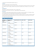
Installation sequence and checklist Step Description 1 Perform site preparation (for information on site preparation, see the HP Integrity rx2800 i2 User Service Guide at ). 2 Install the server into a rack or pedestal. 3 Connect cables to the server. Completed a. Connect the AC input power cable. b. Connect LAN core I/O cable. c. Connect the iLO 3 MP LAN cable. 4 Connect and set up the console for access. 5 Power on the server. 6 From iLO MP, access UEFI. 7 Boot the operating system.
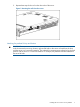
3. Repeat these steps for the rail on the other side of the server. Figure 1 Removing the rails from the server Attaching the pedestal kit top and bottom IMPORTANT: In this document the server top, bottom, right and left refer to the server as faced from the front with the server in a horizontal orientation. The pedestal kit components are referred to by the final position with the server in a vertical orientation. For example, the pedestal kit bottom attaches to the server left side.
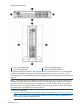
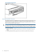
Figure 2 Front of server 1 2 Server top/pedestal right Server left/pedestal top 3 4 Server bottom/pedestal left Server right/pedestal bottom The pedestal kit bottom attaches to the right side of the server when the server is in the horizontal position. The pedestal kit top attaches to the left side of the server when in the server is in the horizontal position. The pedestal bottom can be distinguished from the pedestal top by the pedestal feet slots.
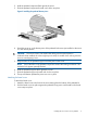
2. 3. Hold the pedestal component flush against the server. Slide the pedestal component forward until it locks into place. Figure 3 Installing the pedestal bottom piece 4. Stand the server up on the bottom piece of the pedestal kit that was just installed so the server is in the vertical position. CAUTION: The server is heavy. Be careful when lifting it to the vertical position. Without the feet installed, the server might tip over easily.
Figure 4 Attaching the bezel Cover Attaching the pedestal kit side pieces The pedestal kit right side piece attaches to the top of the server. The top cover of the server might have ventilation holes in it to enable proper air flow and cooling. The right side piece of the pedestal kit also has ventilation holes in it to enable the proper cooling and air flow. Follow these steps to attach the pedestal kit right side piece.
Figure 5 Attaching the pedestal kit side piece 3. Secure the pedestal side by hand tightening the captive thumb screws on the rear of the server.
Repeat these steps to install the left side piece. Attaching the pedestal feet The pedestal feet slide into the slots on the pedestal bottom, two on each side. The feet are all the same and can be mounted in any slot on the bottom piece of the pedestal kit. Figure 7 Attaching the feet Connecting server cables AC input power The server can receive AC input from two different AC power sources. The power receptacles are located at the rear of the server.
Power states The server has the following power states: • Standby power • Full power • Off Table 2 Power states Power states Power cable plugged into receptacle? Power activated through the iLO 3 PC command; or front panel power button activated? Standby DC DC voltage voltage applied? applied? Standby power Yes No Yes No Full power Yes Yes Yes Yes Off No No No No CAUTION: If the server is expected to remain in standby mode for more than 30 minutes, AC power must be completely remove
Table 3 Setup checklist Step Action Procedure Status Standard setup 1 Preparation 1. Determine an access method to select and connect the cables. 2. Determine a LAN configuration method and assign an IP address if necessary.
After selecting an option, the boot proceeds. NOTE: 3. If no option is selected, the boot proceeds after ten seconds. Depending on how the server was configured from the factory and if the OS is installed at the time of purchase, you are taken to: • UEFI shell prompt • OS login prompt If the server has a factory-installed OS, you can interrupt the boot process to configure your specific UEFI parameters. If you are at the UEFI shell prompt, go to “UEFI Front Page” (page 15).
To configure specific devices, press D to launch the Device Manager. This is an advanced feature and must only be performed when directed. To perform maintenance on the system such as adding, deleting, or reordering boot options, press M to launch the Boot Maintenance Manager.
To perform more advanced operations, press S to launch the UEFI Shell. To view the iLO LAN configuration, press I to launch the iLO Setup Tool. Saving UEFI configuration settings You can configure other UEFI settings at this time. For more UEFI configuration options, see the HP Integrity rx2800 i2 User Service Guide at http://www.hp.com/go/integrity_servers-docs.
Powering on the server using the iLO 3 MP NOTE: If the power restore feature is set to Always On through the iLO 3 MP PR command, the server automatically powers on to the full power state when the power cord is plugged in to the server. 1. 2. 3. 4. 5. 6. Plug all power cables into the receptacles on the rear panel of the server. Initiate a console session, and access the MP Main Menu. Enter CM to enable command mode. Enter PC to use the remote power control command.
Installing the latest firmware using HP Smart Update Manager The HP Smart Update Manager utility enables you to deploy firmware components from either an easy-to-use interface or a command line. It has an integrated hardware discovery engine that discovers the installed hardware and the current versions of firmware in use on target servers. This prevents extraneous network traffic by only sending the required components to the target.
2 Support and other resources Contacting HP Information to collect before you contact HP NOTE: HP recommends that you record any changes that you make to your system, as well as how the changes affect system behavior. 1. 2. 3.
HP contact information For the name of the nearest HP authorized reseller: • See the Contact HP worldwide (in English) webpage (http://www.hp.com/country/us/en/ wwcontact.html). For HP technical support: • • In the United States, for contact options see the Contact HP United States webpage (http:// welcome.hp.com/country/us/en/contact_us.html). To contact HP by phone: ◦ Call 1-800-HP-INVENT (1-800-474-6836). This service is available 24 hours a day, 7 days a week.
proactive notification, but do not need proactive service delivery and integration with a management platform. • HP Insight Remote Support Advanced: This software provides comprehensive remote monitoring and proactive service support for nearly all HP servers, storage, network, and SAN environments, plus selected non-HP servers that have a support obligation with HP. It is integrated with HP Systems Insight Manager.
Book Title The title of a book. On the web and on the Instant Information CD, it may be a hot link to the book itself. KeyCap The name of a keyboard key or graphical interface item (such as buttons, tabs, and menu items). Note that Return and Enter both refer to the same key. Emphasis Text that is emphasized. Bold Text that is strongly emphasized. Bold The defined use of an important word or phrase. ComputerOut Text displayed by the computer. UserInput Commands and other text that you type.
No Parts that are not designed for customer self repair. To satisfy the customer warranty, HP requires that an authorized service provider replace the part. Based on availability and where geography permits, CRU parts are shipped for next business day delivery. Same-day or four-hour delivery might be offered at an additional charge where geography permits. If assistance is required, you can call the HP Technical Support Center and a technician will help you over the telephone.
Standard terms, abbreviations and acronyms ACPI Advanced Configuration and Power Interface. BBWC Battery Backed Write Cache. CMC Corrected machine check. Cold-swappable A component that requires the operating system be shut down and the server powered off before it can be removed. Cold-swappable components are signified with blue touch points. CPE Corrected platform error. CRU Customer Replaceable Unit. DDNS Dynamic DNS. DHCP Dynamic Host Configuration Protocol. DMA Direct memory access.
Index Symbols O 1+1 capability power supplies, 12 online supprt, 21 A PC command, 17, 18 pedestal installing the server into, 6 pedestal bottom attaching, 7 pedestal feet attaching, 12 pedestal sides attaching, 10 pedestal top attaching, 7 phone supprt, 21 power full state, overview, 17 off state, overview, 17 PR command, 17 sources, 12 standby, 13 standby state, overview, 17 states, 13, 17 power reset command see PR command powering off the server, 18 manually, 18 using the iLO 3 MP PC command, 18 pow
U UEFI accessing from iLO MP, 14 Front Page, 15 saving configuration settings, 17 27