
HP Integrity rx2800 i2 Server User Service Guide
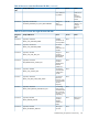

3. Press sl to display the status logs. The status logs consist of:
• System Event
• Forward Progress
• iLO Event
• Clear SEL and FPL
• Live Events
4. For a more information on configuring the iLO 3 MP and using the iLO 3 MP commands, see
the HP Integrity iLO 3 MP Operations Guides.
System event log review
See the HP Integrity iLO 3 Operations Guide for this procedure.
http://www.hp.com/go/integrity_servers-docs
Supported configurations
This subsection provides a system build-up procedure.
System build-up troubleshooting procedure
Use this procedure only when the system powers on and remain powered on but does not enter
into or pass power-on self test (POST) or does not boot to the UEFI menu.
1. Remove the AC power cord from each power supply and extend the server, if racked.
2. Remove all of the SAS disk drives from the front of the server.
3. Remove the top cover to gain access to, and remove all CRUs, except the system board.
NOTE: In the following steps, CRU and FRU are used interchangeably.
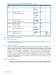
4. Plug in the AC power cords. The iLO 3 MP and system console appears. At the console,
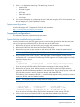
execute the MP DF command. The following CRU IDs appear. Your display might not exactly
match the display shown:
FRU IDs:
--------
00-System Board 02-Display Board 05-Power Supply 1 42-Virtual Connect
If you do not see all of the above CRU IDs then concentrate on the missing CRU IDs.
5. Remove the AC power cords. Add a processor in the CPU 0 socket and add a memory
expansion board with DIMMs populated in slots 4A and 3A. Plug in the AC power cords and
check for the processor, memory expansion board, and DIMM FRU IDs.
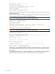
The following is an example of the MP DF command that appears with a processor, memory
expansion board, and two DIMMs installed.
NOTE: Your display might not exactly match the display shown.
FRU IDs:
--------
00-System Board 02-Display Board 05-Power Supply 1
0C-Memory Riser 1 20-Processor 0 24-Processor 0 RAM
42-Virtual Connect 82-DIMM CPU0-R1 3A 83-DIMM CPU0-R1 4A
If you do not see all of the above CRU IDs then concentrate on the missing CRU IDs.
6. Power on the server and check the SEL for any IPMI alerts related to the processor.
NOTE: Your display might not exactly match the display shown.
Supported configurations 83