HP Integrity rx2800 i2 Server User Service Guide Abstract This document contains specific information that is intended for users of this HP product.
© Copyright 2010, 2013 Hewlett-Packard Development Company, L. P. Legal notices The information contained herein is subject to change without notice. The only warranties for HP products and services are set forth in the express warranty statements accompanying such products and services. Nothing herein should be construed as constituting an additional warranty. HP shall not be liable for technical or editorial errors or omissions contained herein.
Table 1 Publishing history details Document Operating systems manufacturing part supported number AH395-9004A • HP-UX Supported product versions Edition number Publication date rx2800 i2 First November 2010 rx2800 i2 Second February 2011 rx2800 i2 Third March 2011 rx2800 i2 Fourth May 2011 rx2800 i2 Fifth August 2011 rx2800 i2 Sixth November 2011 rx2800 i2 Seventh February 2012 rx2800 i2 Eighth August 2012 rx2800 i2 Ninth February 2013 • Microsoft® Windows® AH395-9013A • HP-
Contents 1 Overview................................................................................................10 Server subsystems...................................................................................................................11 Internal components...........................................................................................................11 I/O subsystem...................................................................................................................
OS login prompt................................................................................................................32 Powering on and powering off the server...................................................................................33 Power states......................................................................................................................33 Powering on the server......................................................................................................
Processor load order..........................................................................................................59 Installing a processor and heat sink module..........................................................................59 HP Trusted Platform Module (TPM).............................................................................................64 Verifying installed components in the server...............................................................................
Customer messaging policy............................................................................................88 Troubleshooting the server memory.......................................................................................90 Memory DIMM load order.............................................................................................90 Memory subsystem behaviors..........................................................................................90 Customer messaging policy.......
Removing and replacing a half-length expansion board........................................................119 Removing and replacing a full-length expansion board.........................................................120 Removing and replacing the cache module..............................................................................120 Removing and replacing the super capacitor pack....................................................................121 Removing and replacing the processor baffle....
Set boot next value..........................................................................................................158 Set time out value............................................................................................................159 Reset system....................................................................................................................159 iLO MP...................................................................................................................
1 Overview Table 2 Hardware specifications for the server Component Processors Server One or two Itanium dual-core or quad-core processors: • 1.6-GHz Dual-core Processor 10-MB cache • 1.46-GHz Quad-core Processor 16-MB cache • 1.73-GHz Quad-core Processor 20-MB cache Memory Supports up to twenty-four Double Data Rate 3 (DDR3) DIMMs mounted on expansion boards that attach to the system board.
Server subsystems Internal components Figure 1 Internal components 1 Fans 2 Processors 3 DIMM expansion boards Server subsystems 11
Figure 2 System board components 1 2 3 4 5 6 7 8 9 12 Overview Memory expansion board connector 1 Memory expansion board connector 2 Processor socket 0 Processor socket 1 SATA optical drive connector CPU 0 power connector Front I/O connector Power supply backplane connector Intrusion switch connector 10 11 12 13 14 15 16 17 18 Primary riser connector TPM connector System battery SAS B connector SAS A connector Secondary riser connector SAS cache module connector SAS power connector CPU 1 power connect
Figure 3 Internal USB location I/O subsystem The I/O subsystem consists of the core I/O and two optional I/O riser boards. Wake-on-LAN is not enabled on any PCIe Public slots. The server does not support PCI Hot Plug (PHP). The standard I/O Riser supports one full-height, full-length PCIe x8 and two full-height, half-length PCIe x4 add-in cards. The second riser option supports one full-height, full-length PCIe x8, and one full-height, half-length PCIe x8 add-in cards.
NOTE: To use all 8 disks with the zero memory option, the following RAID configurations are supported: – RAID 0: 1 or 2 LUNs striped with up to 8 disks – RAID 10: 1 or 2 LUNs striped and mirrored with even number of up to 8 disks – RAID 1: 1 LUN using 2 mirrored disks, and one additional LUN in RAID 0 or 10 Example configurations of eight disks with zero memory • – LUN 1: RAID 1 bays 1 and 2 – LUN 2: RAID 0 bays 3, 4, 5, 6, and 7 – Hot Spare: bay 8 – LUN 1: RAID 10 bays 1, 2, 3, and 4 – LUN
Storage and media devices The server supports up to eight hot-plug SAS HDDs, and one optical (SATA DVD+RW) drive, with LEDs that indicate activity and device statuses. Figure 5 SAS device numbers Rear panel controls and ports The server rear panel includes communication ports, I/O ports, USB ports, AC power connectors, and the locator LED and button. LEDs located on the rear panel of the server signal the operational status of the rear panel components.
2 Site preparation For information on general computer room site preparation, see the HP Generalized Site Preparation Guide on the HP website: http://www.hp.com/go/Integrity_Servers-docs IMPORTANT: To avoid hardware damage, allow the thermal mass of the product to equalize to the temperature and humidity of the installation facility after removing the shipping materials. A minimum of one hour per 10° C (50° F) of temperature difference between the shipping facility and installation facility is required.
Table 4 System power specifications (continued) Parameter +12VSB /2.5A MAX +12VSB /2.5A MAX +12VSB /2.5A MAX If an overload triggers the power supply overload protection, the system is immediately powered off. To reset the power supply unit: 1. Disconnect the power cord. 2. Determine what caused the overload by contacting an HP support representative. 3. Reconnect the power cord. 4. Reboot the system. NOTE: If an overload occurs twice, an undetected short circuit exists.
Table 7 Environmental specifications (system processing unit with hard disk) (continued) Value Parameter Data Center Server Office Friendly Server Over-temperature shutdown +38° C (+100° F) Operating humidity 15% to 80% RH noncondensing Non-operating humidity 8% to 90% RH at 65° C noncondensing Acoustic Noise Emission (ISO 9296) Sound Power Level Maximum configuration (disk active)2 LwAd = 7.0 B LwAd = 6.0 B Sound Pressure Level LpAm = 52.7 dB LpAm = 42.
Unpacking the server 1. 2. Follow the instructions printed on the outside top flap of the carton to remove the banding and the outer carton from the server pallet. Remove all inner accessory cartons and the top foam cushions, leaving only the server. IMPORTANT: Inspect each carton for shipping damage as you unpack the server. Verifying the inventory The sales order packing slip lists all the equipment shipped from HP. Use this packing slip to verify that all equipment has arrived.
3 Installing the server Safety information Follow the instructions carefully to prevent injury and equipment damage when performing removal and replacement procedures. Voltage might be present within the server. Many assemblies are sensitive to damage by ESD.
Step Description 3 Connect cables to the server. Completed a. Connect the AC input power cable. b. Connect LAN core I/O cable. c. Connect the iLO 3 MP LAN cable. 4 Connect and set up the console for access. 5 Power on the server. 6 From iLO MP, access UEFI. 7 Boot the operating system. 8 Using HP Smart Update Manager, download the latest firmware.
3. Repeat these steps for the rail on the other side of the server. Figure 7 Removing the rails from the server Attaching the pedestal kit top and bottom IMPORTANT: In this document the server top, bottom, right and left refer to the server as faced from the front with the server in a horizontal orientation. The pedestal kit components are referred to by the final position with the server in a vertical orientation. For example, the pedestal kit bottom attaches to the server right side.
Figure 8 Front of server 1 2 Server top/pedestal right Server left/pedestal top 3 4 Server bottom/pedestal left Server right/pedestal bottom The pedestal kit bottom attaches to the right side of the server when the server is in the horizontal position. The pedestal kit top attaches to the left side of the server when in the server is in the horizontal position. The pedestal bottom can be distinguished from the pedestal top by the pedestal feet slots.
2. 3. Hold the pedestal component flush against the server. Slide the pedestal component forward until it locks into place. Figure 9 Installing the pedestal bottom piece 4. Stand the server up on the bottom piece of the pedestal kit that was just installed so the server is in the vertical position. CAUTION: The server is heavy. Be careful when lifting it to the vertical position. Without the feet installed, the server might tip over easily.
Figure 10 Attaching the bezel Cover Attaching the pedestal kit side pieces The pedestal kit right side piece attaches to the top of the server. The top cover of the server might have ventilation holes in it to enable proper air flow and cooling. The right side piece of the pedestal kit also has ventilation holes in it to enable the proper cooling and air flow. Follow these steps to attach the pedestal kit right side piece.
Figure 11 Attaching the pedestal kit side piece 3. Secure the pedestal side by hand tightening the captive thumb screws on the rear of the server.
Repeat these steps to install the left side piece. Attaching the pedestal feet The pedestal feet slide into the slots on the pedestal bottom, two on each side. The feet are all the same and can be mounted in any slot on the bottom piece of the pedestal kit. Figure 13 Attaching the feet Connecting server cables AC input power The server can receive AC input from two different AC power sources. The power receptacles are located at the rear of the server.
Power states The server has the following power states: • Standby power • Full power • Off Table 8 Power states Power states Power cable plugged into receptacle? Power activated through the iLO 3 PC command; or front panel power button activated? Standby DC DC voltage voltage applied? applied? Standby power Yes No Yes No Full power Yes Yes Yes Yes Off No No No No CAUTION: If the server is expected to remain in standby mode for more than 30 minutes, HP recommends completely removing
Setup checklist Use the checklist in Table 9 while setting up the Integrity iLO 3. Table 9 Setup checklist Step Action Procedure Status Standard setup 1 Preparation 1. Determine an access method to select and connect the cables. 2. Determine a LAN configuration method and assign an IP address if necessary.
NOTE: The prompt might take several minutes to appear, and the period that you can press Ctrl-C is very short. For typical boots, HP recommends that you let the prompt time out. After selecting an option, the boot proceeds. NOTE: 3. If no option is selected, the boot proceeds after ten seconds.
To view boot options, or launch a specific boot option, press B to launch the Boot Manager. To configure specific devices, press D to launch the Device Manager. This is an advanced feature and must only be performed when directed. To perform maintenance on the system such as adding, deleting, or reordering boot options, press M to launch the Boot Maintenance Manager.
To perform more advanced operations, press S to launch the UEFI Shell. To view the iLO LAN configuration, press I to launch the iLO Setup Tool. Saving UEFI configuration settings You can configure other UEFI settings at this time. For more UEFI configuration options, see Appendix A (page 145).
Powering on and powering off the server Power states The server has the following power states: • Standby power • Full power • Off For details about server power states, see Table 8 (page 28). NOTE: If the power restore feature is set to Always On through the iLO 3 MP PR command, the server automatically powers on to the full power state when the power cord is plugged in to the server.
Powering off the server using the iLO 3 MP 1. 2. 3. 4. 5. Gracefully shut down the operating system. See the operating system documentation for more information. Initiate a console session, and access the MP Main Menu. Enter CM to enable command mode. Enter PC to use the remote power control command. Enter OFF to power off the server, and enter YES when prompted to confirm the action.
Troubleshooting installation issues To troubleshoot issues that might occur during server installation, see “Installation troubleshooting” (page 85).
4 Operating system procedures Operating systems supported on the server • HP-UX 11i v3 HWE 1009 or later • HP OpenVMS v8.4 with VMS84I_UPDATE-V0500, rx2800 i2 enablement kit • Windows Server 2008 Itanium Edition R2 NOTE: Wake-On-LAN (WOL) is supported with Integrity rx2800 i2 Servers running HP-UX 11i v3. WOL is not supported with Integrity servers running Windows or OpenVMS environments. The supported remote power-on solution for Windows and OpenVMS environments is iLO 3.
4. Locate the device you want to boot from. a. For DVD, locate the device: i. To list all device names from the UEFI Shell prompt, use the map command. ii. From the list generated by the map command, locate the device name (in this example, fs6). fs2:\> map Device mapping table fs6 :Removable CDRom - Alias cd66d0a blk6 PcieRoot(0x30304352)/Pci(0x1D,0x7)/USB(0x3,0x0)/CDROM(0x0) NOTE: Your DVD drive might not be named fs6. Make sure you verify the ID appropriate to your DVD device. iii.
Installing HP OpenVMS with Infoserver Utility Infoserver Utility enables OpenVMS installations and upgrades over the network. To install the OS using Infoserver, see the "Setting Up and Performing Network Booting" section in HP OpenVMS Version 8.4 Upgrade and Installation Manual on the HP website: http://h71000.www7.hp.com/doc/84final/ba322_90087/ba322_90087.
Booting and shutting down HP-UX • To add an HP-UX entry to the boot options list, see “Adding HP-UX to the boot options list” (page 39). • To boot HP-UX, use one of the following procedures: • ◦ To boot HP-UX in the standard mode, see “HP-UX standard boot” (page 40). HP-UX boots in multi-user mode. ◦ To boot HP-UX in single-user mode, see “Booting HP-UX in single-user mode” (page 41). ◦ To boot HP-UX in LVM-maintenance mode, see “Booting HP-UX in LVM-maintenance mode” (page 41).
• bcfg boot mv #a #b–Move the item number specified by #a to the position specified by #b in the boot options list. • bcfg boot add # file.EFI "Description"–Add a new boot option to the position in the boot options list specified by #. The new boot option references file.EFI and is listed with the title specified by Description. For example, bcfg boot add 1 \EFI\HPUX\HPUX.EFI "HP-UX 11i v3" adds an HP-UX 11i v3 item as the first. For details, see the help bcfg command. 4.
6. Allow the HPUX.EFI loader to proceed with the boot command specified in the AUTO file, or manually specify the boot command. By default, the HPUX.EFI loader boots using the loader commands found in the \EFI\HPUX\ AUTO file on the UEFI System Partition of the selected boot device. The AUTO file typically contains the boot vmunix command. To interact with the HPUX.EFI loader, interrupt the boot process (for example, enter a space) within the time-out period provided by the loader.
Booting and shutting down HP OpenVMS Adding OpenVMS to the Boot Options list NOTE: If OpenVMS is already installed on the server, add OpenVMS to the boot options list by using the SYS$MANAGER:BOOT_OPTIONS.COM command procedure, and follow the on-screen instructions. NOTE: 1. Commands are not case-sensitive. Access the UEFI Shell environment. a. Log in to iLO for Integrity, and then to access the system console, enter CO. When accessing the console, confirm that you are at the UEFI Front Page.
Booting OpenVMS from the UEFI Boot Manager 1. 2. 3. 4. 5. From the UEFI Boot Manager menu, using the chosen boot option, choose an item from the boot options list to boot OpenVMS. Access the UEFI Boot Manager menu for the server on which you want to boot OpenVMS. Log in to the iLO MP, and then to choose the system console, enter CO. Confirm that you are at the UEFI Front Page. If you are at another UEFI menu, then to exit the menu, choose the Exit option or press X.
2. At the OpenVMS DCL prompt, enter the @SYS$SYSTEM:SHUTDOWN command, and then specify the shutdown options in response to the prompts given. NOTE: Use the command in step 2 when you shut down OpenVMS for the first time. If you have shut down OpenVMS more than once, use the $ shutdown command.
4. Use the \MSUtil\nvrboot.efi command to launch the Microsoft Windows boot options utility. fs0:\> msutil\nvrboot NVRBOOT: OS Boot Options Maintenance Tool [Version 5.2.3683] 1. 2. * 3. 4. SUSE SLES 10 HP-UX Primary Boot: 0/0/1/0/0.2.0 Windows Server 2003, Datacenter EFI Shell [Built-in] * = Windows OS boot option (D)isplay (M)odify (C)opy E(x)port (I)mport (E)rase (P)ush (H)elp (Q)uit Select> 5. Use the Import command to import the Window boot option file.
SAC> NOTE: 8. Your output might not exactly match the output shown here. Exit the console and iLO MP interfaces when finished using them. Enter Ctrl-B to exit the console and return to the iLO MP Main menu. To exit the iLO MP, enter X at the Main menu. Shutting down Microsoft Windows Shut down the Windows operating system on HP Integrity servers by using the Start menu or the shutdown command. CAUTION: Do not shut down Windows using SAC restart or shutdown commands under normal circumstances.
3. Issue the shutdown command and the appropriate options to shut down the Windows Server 2003 on the server. You have the following options when shutting down Windows: • To shut down Windows and reboot: shutdown /r or choose the Start —> Shut Down action and choose Restart from the pull-down menu. • To shut down Windows and halt (power off server hardware): shutdown /s or choose the Start —> Shut Down action and choose Shut down from the pull-down menu.
5 Optional components This section describes how to install components into the server that are not factory-installed. If you have additional components to install, be sure to install the additional components before installing the server into your rack or pedestal configuration. Most servers are pre-configured with all components installed before shipping from the HP factory.
2. To install the hard drive, push in the drive and then close the locking lever. Installing a hot-swappable power supply The server has at least one hot-swappable power supply installed before shipping. This power supply is located at the rear of the server. You can install a second, optional power supply to provide 1+1 capability. Figure 14 Power supply loading guidelines 1 Power supply bay 2 2 Power supply bay 1 CAUTION: Observe all ESD safety precautions before attempting this procedure.
1. Remove the power supply blank. 2. Install the power supply. Removing the access panel 1. 50 Use the T-15 Torx screwdriver attached to the rear of the server to loosen the security screw on the hood latch.
2. Lift the hood latch handle, and then remove the access panel. To replace the component, reverse the removal procedure. Removing the PCI riser cage CAUTION: For proper cooling, do not operate the server without the access panel, baffles, expansion slot covers, or blanks installed. If the server supports hot-pluggable components, minimize the amount of time the access panel is open. 1. 2. Disconnect any cables connected to optional I/O cards before removing cage. Remove the PCI riser cage.
Removing expansion slot covers CAUTION: To prevent damage to the server or expansion boards, power off the server, and then remove all AC power cords before removing or installing the PCI riser cage. CAUTION: For proper cooling, do not operate the server without the access panel, baffles, expansion slot covers, or blanks installed. If the server supports hot-plug components, minimize the amount of time the access panel is open. 1. 2. 3. 52 Remove the access panel (“Removing the access panel” (page 50)).
Installing expansion boards The server supports up to two PCIe riser boards. Each PCIe riser board holds up to three PCIe cards. The standard riser board configuration contains one riser board with one full-length, full-height PCIe x8 slot, and two half-length, full-height PCIe x4 slots. The second board contains one full-length, full-height PCIe x8 slot, and two half-length, half-height PCIe x4 slots. Optionally, you can purchase a riser board that contains two full-length PCIe x8 slots.
5. 6. 7. Connect any required internal cables to the expansion board. Reinsert the PCI riser cage into the chassis. Connect any required external cables to the expansion board. Installing DIMMs Memory configurations The server has 24 system memory DIMM slots located on 4 memory expansion boards (6 DIMMs per expansion board). You can access the memory expansion boards without removing the airflow guide or the I/O card cage. The DIMMs are partitioned by the number of processors installed in the server.
Table 10 Memory Load Order 2 Processor system (socket 0 and 1) Memory slots 1 Processor system (socket 0) Pair number Memory expansion board Memory expansion board Memory slots 1 Memory expansion board 1 3A and 4A Memory expansion board 1 3A and 4A 2 Memory expansion board 3 3A and 4A Memory expansion board 2 3A and 4A 3 Memory expansion board 2 3A and 4A Memory expansion board 1 1B and 6B 4 Memory expansion board 4 3A and 4A Memory expansion board 2 1B and 6B 5 Memory expansion b
Memory loading rules and guidelines CAUTION: Failure to observe the following cautions results in system degradation or failure: • Only ECC DIMMs are supported. • Load DIMM pairs from largest to smallest capacity. For example, if you have a pair of 4 GB DIMMs and a pair of 2 GB DIMMs, install the pair of 4 GB DIMMs first. NOTE: Faster DIMMs and slower DIMMs can be installed on different slots within the same channel, but faster DIMMs operate at the timing of the slowest DIMM populated.
3. Install the DIMM.
4. Replace the memory expansion board. CAUTION: Be sure to align the three stand-offs in the alignment slots. TIP: If you see abnormal error lights after installing DIMMs, try uninstalling and reinstalling the DIMMs and the memory expansion board to make sure the DIMMs and memory expansion board are correctly seated. Installing a processor The server can use dual-core or quad-core processors. Dual-core processors contain two cores that function as separate processors.
Processor load order The server holds up to two dual-core or quad-core processors on the system board. The sockets on the system board are labeled Module 0 and Module 1. If the server has only one processor, it is installed in socket 0. Install the second processor in socket 1. See Figure 2 (page 12) for the processor socket numbers.
3. Transfer the duplicate part/serial numbers label from the processor module to the processor heat sink: a. Remove the duplicate tear-away label that lists the part and serial numbers from the processor module. b. Place the label on the top of the heat sink. 4. Install the processor over the load posts. NOTE: Ensure pin 1, indicated on the empty socket with an embossed triangle, matches the pin 1 marker on the processor module, the chamfered corner of its attached voltage regulator heat sink. 5.
CAUTION: To avoid damage to the server and processor, ensure the processor heat sink locking handle is fully back against the stops, rotated approximately 120° back. Also, verify that the plastic tabs on the processor heat sink are fully pulled out before installation. 6. Install the heat sink over the load posts. CAUTION: into place.
CAUTION: To prevent thermal instability and damage to the server, do not separate the processor module from the processor heat sink after they have been coupled. NOTE: Positive engagement clicking must occur during engaging of the processor heat sink and processor module onto the socket to ensure proper seating.
7. Secure the heat sink to the processor. a. Slide both plastic locking tabs into place. See callout 1 in the following figure. b. Flip the latch down. See callout 2 in the following figure. WARNING! The heat sink locking lever can constitute a pinch hazard. Keep your hands on top of the lever during installation to avoid personal injury. CAUTION: To prevent thermal instability and damage to the server, do not separate the processor module from the processor heat sink after they have been coupled. 8.
9. Tie wrap the processor cable to the right tie point on the processor assembly. CAUTION: When the processor is installed, dress all slack in the power cable to the connector end of the cable. Failure to do so can result in pinched or damaged processor power cables. NOTE: If you are adding an additional processor to your server, the DIMMs in the server must be reconfigured to support both processors. For more information, see “Memory configurations” (page 54).
3. Enter info all from the UEFI Shell prompt. The following appears: NOTE: Your display might not match the display shown.
Boottest: BOOTTEST Settings Default Variable OS is not speedy boot aware.
6 Troubleshooting The purpose of this chapter is to provide a preferred methodology (strategies and procedures) and tools for troubleshooting the server error and fault conditions. How to contact HP For information on how to contact HP, see “Contacting HP” (page 139).
You might have to perform specific recovery procedures to finish the repair. For example, if the system board is replaced, you need to restore customer specific information. Should a failure occur, the System Insight Display LEDs, SEL and FPL help you identify the issue or CRU: • LEDs. The front panel LEDs and LAN LEDs of the server change color and blink to help identify specific issues. • The System Event Log (SEL) provides detailed information about the errors identified by the LEDs.
Table 12 Troubleshooting entry points (continued) Entry point Subsection or location Offline and Online Diagnostics/INIT button “Troubleshooting tools” (page 72) System Event Analyzer “Troubleshooting tools” (page 72) (see also http://www.compaq.com/ support/svctools/webes/ for more information about this tool) Basic and advanced troubleshooting tables The following troubleshooting tables are designed for use by both trained and untrained support personnel.
Table 13 Basic low end troubleshooting (continued) Step Condition Action green, replace power supply (see “Troubleshooting the power subsystem” (page 91)for details). The preceding issue is fixed when the failure condition is corrected, and the front panel LED states are as follows: system health is steady green, and power is steady green. 3 System health LED is flashing red.
Table 13 Basic low end troubleshooting (continued) Step Condition Action The preceding issue is fixed when iLO 3 MP menu appears on the system console, and the system health is steady green. 4b Cannot see UEFI prompt on system console. Nothing might be logged for this condition (system health is steady green, and power is steady green). 1. Examine the SID LEDs for any faults. 2.
Table 14 Advanced low end troubleshooting Step Symptom/Condition Action 6 Cannot read System Event Log from the iLO console. System event logging has stopped and a iLO MP malfunction is assumed (system health is steady green, and power is steady green). 1. Examine console messages for any UEFI errors or warnings about iLO operation or communications. 2.
LEDs Front panel LEDs Figure 16 Front panel LEDs and buttons 1 UID LED and button 2 System health LED 3 Power button Table 15 Front panel controls Name Function Status UID button This button helps locate a particular server within a rack of servers. You can remotely activate this function through various system utilities.
There are a total of three LEDs, arranged vertically, with the UID button and the power button each having an integrated LED. In addition to the two integrated button/LEDs, there is a health LED. System health LED The front panel health LED indicates the status of the components that are externally serviceable. Whenever the system health LED illuminates, the corresponding CRU illuminates for the failed component.
Figure 17 System Insight Display LEDs Table 18 SID LED states LED State NICs • Off = No link to network • Flashing green = Network link and activity • Green = Network link Power Cap Over Temp NOTE: This LED is not used. Power capping operation can be observed through iLO 3. For more information, see the HP Integrity iLO 3 Operations Guide.
Table 19 SID LED States Definition Flash Rate LED Color CRU health is assumed good. LED Off Off CRU health last known to be bad. Steady Amber NOTE: The Power Supply LED illuminates only when a failure or fault is detected in a power supply. Loss of AC power to a power supply will generate a SEL entry, but does not result in the Power Supply LED illuminating.
Drive status LED The drive status LED can appear amber or blue. • Amber indicates a warning, or failure condition. • Blue is a locator LED that identifies a particular disk drive. Various software utilities, such as online diagnostics or SAS disk drive configuration tools, can activate the locator LED.
Optical drive The server has one SATA DVD+RW drive. This device has one activity LED.
Table 23 Rear panel LEDs and buttons (continued) Name Status • A greater than 8-second and less than 12-second press of this button places iLO into security override mode for up to 15 minutes. Security override mode enables you to enter iLO without being challenged for a password enabling you to set up users. • The UID LED blinks once after holding the button for 4 seconds and once after holding the button for 8 seconds to help you gauge how long the button press has been held.
Information modules create a log of information specific to one device, including: • The product identifier • A description of the device • The hardware path to the device • The vendor • Onboard log information (if applicable) • Miscellaneous information associated with the device • The firmware revision code, if firmware is present in the device, is also displayed Expert tools are device-specific troubleshooting utilities for use by sophisticated users.
Fault management overview The goal of fault management and monitoring is to increase system availability, by moving from a reactive fault detection, diagnosis, and repair strategy to a proactive fault detection, diagnosis, and repair strategy. The objectives are as follows: • To detect issues automatically, as nearly as possible to when they actually occur. • To diagnose issues automatically, at the time of detection.
Errors and reading error logs Event log definitions Often the underlying root cause of an MCA event is captured by system or iLO MP firmware in both the System Event and Forward Progress Logs (SEL and FPL, respectively). These errors are easily matched with MCA events by their timestamps. For example, the loss of a processor VRM might cause a processor fault. Decoding the MCA error logs would only identify the failed processor as the most likely faulty CRU.
3. 4. Press sl to display the status logs. The status logs consist of: • System Event • Forward Progress • iLO Event • Clear SEL and FPL • Live Events For a more information on configuring the iLO 3 MP and using the iLO 3 MP commands, see the HP Integrity iLO 3 MP Operations Guides. System event log review See the HP Integrity iLO 3 Operations Guide for this procedure. http://www.hp.com/go/integrity_servers-docs Supported configurations This subsection provides a system build-up procedure.
Log Entry 4: 01 Aug 2012 17:22:00 Alert Level 7: Fatal Keyword: BOOT_NOT_DETECTED No events were received from system firmware Logged by: integrated Lights Out Sensor: Processor Data1: FRB2/Hang in POST failure 20501965B8020006 FFFF036F00070400 If the above Level 7 IPMI alert appears, verify the installation of your processor and if necessary replace the processor. 7.
9. If the processor, memory expansion board, and DIMMs are all installed and functioning correctly, the system boots to UEFI. The following messages appear in the SEL. NOTE: Your display might not exactly match the display shown.
Table 28 Server power button functions when server is on and OS is running Action Reaction 1-3 seconds System power turns off (software-controlled power off) 5 seconds or longer System power turns off immediately (hard power off) If the server is off, and power is not connected to the server power supplies, pressing the power button has no effect. If the server is off, and power is connected to server power supplies, the front panel power LED flashes at a 1 Hz rate.
Operating system boots with issues If the operating system is running and you are experiencing issues, use the following tools to resolve the issue: • LEDs • Error Messages and event logs Intermittent server issues You can usually trace intermittent issues that occur during installation to power source issues, a loose connector, or some other hardware issue. If you are experiencing intermittent issues: 1. View iLO 3 MP logs and analyze the issue.
Troubleshooting the processor and memory All of the processor and memory controller functions are integrated into the processor. DIMMs reside on the memory expansion boards, and PCIe bus controller chips reside on the I/O riser and the system board. This section discusses the roles of logical processors, and physical memory ranks. Troubleshooting the server processor The server supports both dual-core and quad-core processors. Each server supports one or two processor modules.
Table 30 Processor events that illuminate SID LEDs (continued) Diagnostic LEDs Sample IPMI Events Cause Source errors detected by platform Processors Type 02h, 02h:07h:03h VOLTAGE_DEGRADES_TO_NON_RECOVERABLE Voltage on CRU is inadequate Notes cache errors from processor corrected by ICH10 iLO MP Power Pod voltage is out of range (likely too low) Table 31 Processor events that might illuminate SID LEDs Diagnostic LEDs Sample IPMI Events Cause Source Processors Type E0h, 734d:26d Installed pr
Table 31 Processor events that might illuminate SID LEDs (continued) Diagnostic LEDs Sample IPMI Events Cause Source Notes processor (thread) has timed out Processors Type E0h, 57d:26d BOOT_INCOMPATIBLE_SLAVE Processor Type E0h, 56d:26d BOOT_INCOMPATIBLE_ PAL Processors Type E0h, 34d:26d BOOT_CPU_FAILED Processors Type E0h, 33d:26d BOOT_CPU_EARLY_TEST_FAIL Processors Type 02h, 25h:71h:80h MISSING_FRU_DEVICE A logical slave processor (thread) is incompatible with logical monarch processor SFW
actions, and the DIMM CRU LED for the suspect DIMM on the System Insight Display is not lit. • For configuration-type errors, for example, the CRU LEDs on the SID LED panel illuminate for all DIMMs that are not installed. • No diagnostic messages are reported for single-byte errors that are corrected in both ICH10 caches and DIMMs during CPE events.
1. 2. 3. 4. 5. 6. 7. Power LED on front panel glows steady amber when one or two bulk power supplies are plugged into nominal AC voltage and the +3.3 VDC housekeeping voltage comes on and stays on whenever AC power is present. The iLO 3 MP, Flash memory, and server intrusion circuits are reset after the +3.3 V DC housekeeping voltage stabilizes. The iLO 3 MP monitors the power button on the front panel. When the power button is pressed, iLO 3 signals the bulk power supplies to fully power up.
Cooling subsystem behavior The iLO 3 MP controls fan speed on ambient air temperatures, chip temperatures, server configuration, and fan operation or failure. Air is drawn through the front of the server and pushed out the rear by the cooling fans. You can display fan status remotely with the iLO 3 MP ps command. Within the server, temperature sensors report server temperatures to iLO 3, which controls fan speed based on this information.
Table 37 I/O card events that might illuminate SID LEDs Diagnostic LEDs Sample IPMI Events Cause Source Notes I/O Card Type E0h, 4658d:26d A non hot plug I/O slot power consumption increases the total I/O power consumption beyond the supported limit SFW Disallow O/S boot and display the following UEFI error message, "I/O configuration exceed" Insufficient power to power on a hot-plug PCI-X slot SFW Display UEFI warning message "Failed I/O slots deconfigured" PCI slot standby power failed SFW
Table 37 I/O card events that might illuminate SID LEDs (continued) Diagnostic LEDs Sample IPMI Events Cause Source I/O Card Type E0h, 143d:26d SFW IO_ROPE_RESET_ERROR I/O rope reset failed to complete Type E0h, 7346d PCIe link failed to train SFW PCIe link is not running at max capable bandwidth SFW I/O Card Notes CC_IODISC_LBA_LINK_TRAIN_ERR I/O Card Type E0h, 7356d IO_PCIE_LINK_SUBOPTIMAL Troubleshooting the iLO 3 MP subsystem This subsection provides information on troubleshooting issu
System LAN LEDs Four system LANs are located on the rear bulkhead of the server. These LANs are connected to the system board. Table 39 Gb LAN connector LEDs LED Description Link (left) Green: link Off: no link Activity (right) Green: link Off: No link Troubleshooting the boot process Table 40 Normal boot process LED states Step System Event Log Health Power SID Normal power-up through OS boot 1 Off Off Off Off No AC power to the system.
5. UEFI Shell is launched from shared memory, and cache lines are retrieved 128 bytes at a time by MEMC in ICH10. 6. OS loader is launched using the UEFI device driver. 6. OS boots and starts its own device drivers. 6. OS can use runtime PAL and SAL calls, and APCI features (these abstraction layers enable platform independence).
2. Choose the appropriate firmware package from the choices available on the HP Support Center web page at http://www.hp.com/go/bizsupport. To verify the firmware version, see the Release Notes or Installation Instructions. To update firmware by using HP Smart Update Manager, see “Installing the latest firmware using HP Smart Update Manager” (page 34). Troubleshooting the system console All system console connections (VGA, USB, local RS-232 and iLO 3 MP LAN) are located on the rear panel of the server.
7 Removal and replacement procedures Server components list IMPORTANT: Part numbers are found by using the part nomenclature from this list to select the correct part from HP Partsurfer (http://www.partsurfer.hp.com/search.aspx). To select a replacement part from the full component list, enter the product number for your system. Table 41 CRU list Description Spare part number Processors Intel Itanium 1.6-GHz Dual-core processor 10-MB cache AH339-6914A Intel Itanium 1.
Table 41 CRU list (continued) Description Spare part number SAS Disk Backplane 507690-001 Power Supply Backplane 496062-001 Fans Replacement, Fan Module Assembly AH395-67003 Cables Replacement Cable Kit, includes: AH395-67002 • Intrusion Switch and Cable • SID Ribbon Cable • SAS Backplane Power Cable SATA optical drive power/signal combo cable 496071-001 Cache super capacitor and cable 587324-001 Mini SAS connector and cable x2 498425-001 I/O PCA, PCIe 2D FireMV2250 Graphics (Future release
Table 41 CRU list (continued) Description Spare part number Replacement, Air Blocker Cover AH395-67005 DVD Blank 496058-001 SAS Cache Memory Module 512 MB 578882-001 HDD cage and bezel 496074-001 System battery (CR2032) 153099-001 1 Must be replaced with a new processor. CAUTION: FRU components are not customer-serviceable. You must contact an HP authorized service provider to install or replace these components.
Preparation procedures To access some components and perform certain service procedures, you must perform one or more of the following procedures: • Extend the server from the rack (“Extending the server from the rack” (page 102)). If you are performing service procedures in an HP, Compaq branded, Telco, or third-party rack cabinet, you can use the locking feature of the rack rails to support the server and gain access to internal components.
3. After performing the installation or maintenance procedure, slide the server back into the rack, and then press the server firmly into the rack to secure it in place. WARNING! To reduce the risk of personal injury, be careful when pressing the server rail-release latches and sliding the server into the rack. The sliding rails might pinch your fingers. Accessing internal components for a pedestal-mounted server 1. 2. Power off the server and remove all cables. Remove the pedestal kit feet.
Figure 20 Removing the pedestal kit feet 3. 4. Lay the server on the left side (facing the front of the server). The right side of the pedestal kit (with the ventilation holes) must face up. Unscrew the captive thumbscrews on the rear of the pedestal kit for the right side pedestal kit piece.
Figure 21 Thumbscrew locations 5. To remove the pedestal kit piece from the pedestal, slide the right side piece toward the back of the server, and then lift it.
6. Remove the server access panel. Figure 23 Access panel removal Powering off the server WARNING! To reduce the risk of personal injury, electric shock, or damage to the equipment, remove the power cord to remove power from the server. The front panel Power On/Standby button does not completely shut off system power. Portions of the power supply and some internal circuitry remain active until AC power is removed. NOTE: 1. 2. If installing a hot-plug device, you do not have to power off the server.
Removing the server from the pedestal kit Required tools No tools are required for disassembling the pedestal kit. Power off the server and remove cables 1. 2. Power off the server (“Powering off the server” (page 106)). Disconnect the power and LAN cables connected to the server. Removing the pedestal kit 1. Remove pedestal feet. Figure 24 Removing the pedestal kit feet 2.
Figure 25 Thumbscrew locations Figure 26 Removing the side piece 3. Release the locking tabs behind the top corners of the bezel cover and remove the component.
Figure 27 Removing the bezel cover 4. Remove the pedestal top piece. a. With the server still in the vertical position, look at the left side of the server (server bottom) to locate the lock release tab. b. Press the lock release tab on the pedestal top piece away from the chassis to unlock the pedestal top piece from the server. See Figure 28 for the pedestal top and bottom piece lock release locations. Figure 28 Removing the pedestal top piece c. d. e. f.
Accessing the product rear panel Cable management arm with left-hand swing 1. Remove the cable arm retainer. 2. Open the cable management arm. Cable management arm with right-hand swing NOTE: To access some components, you might have to remove the cable management arm. To access the product rear panel components, open the cable management arm: 1. Power off the server (“Powering off the server” (page 106)). 2. Swing open the cable management arm. 3. Remove the cables from the cable trough.
4. Remove the cable management arm. Removing and replacing a SAS hard drive blank CAUTION: For proper cooling do not operate the server without the access panel, baffles, expansion slot covers, or blanks installed. If the server supports hot-plug components, minimize the amount of time the access panel is open. Remove the component as indicated. Figure 29 Hard drive filler removal To replace the blank, slide the blank into the bay until it locks into place.
3. Remove the hard drive. To replace the component, see “Installing a hot-pluggable SAS hard drive” (page 48). Removing and replacing a power supply blank CAUTION: To prevent improper cooling and thermal damage, do not operate the server unless all bays are populated with either a component or a blank. To remove the component: Figure 30 Removing the blank To replace the component, reverse the removal procedure.
1 A maximum of 8 DIMMs are supported in a configuration with low line AC voltage and 2 processors. NOTE: Configurations other than those listed in Table 43 (page 112) do not have 1+1 power redundancy and are not supported. Power redundancy is dependent on the number of power supplies, processors, and DIMMs in a system. Additional components, such as HDDs or PCIe cards, do not impact power redundancy. The server also supports power capping. Power capping operation can be observed through iLO 3.
Removing and replacing the optical drive filler To remove the component: CAUTION: To prevent improper cooling and thermal damage, do not operate the server unless all bays are populated with either a component or a blank. 1. 2. 3. 4. 5. Power off the server (“Powering off the server” (page 106)). Extend or remove the server from the rack. Remove the access panel. See “Removing the access panel” (page 50). Remove the fans 2 and 3. See “Removing and replacing a hot-swap fan” (page 115).
6. Lift the DVD release tab, and push out the drive. Then pull the drive straight out to remove it from the server. To replace the component, reverse the removal procedure. The optical drive cable routes beneath fan 2. Removing and replacing a hot-swap fan Six fans cool the server. The fans are all redundant, hot-swappable, and interchangeable. If one fan unit fails, then the other fans increase speed to compensate.
Figure 31 Fan identification The power supplies have built-in fans and are not controlled by the iLO MP. For fan identification, see Figure 31 (page 116). 1. Extend or remove the server from the rack (“Removing the server from the rack” (page 106) or “Extending the server from the rack” (page 102)). 2. Remove the access panel (“Removing and replacing the access panel” (page 113)). 3. Remove the fan. CAUTION: Do not operate the server for long periods with the access panel open or removed.
3. 4. 5. 6. 7. Extend or remove the server from the rack (“Removing the server from the rack” (page 106)) or “Extending the server from the rack” (page 102)). Remove the access panel (“Removing the access panel” (page 50)). Remove the PCI cage (“Removing the PCI riser cage” (page 51)). Remove the necessary memory expansion boards (“Installing DIMMs” (page 56)). Remove the power supply backplane. To replace the component, reverse the removal procedure. Removing and replacing the hard drive backplane 1. 2.
6. Remove the hard drive backplane. To replace the component, reverse the removal procedure. CAUTION: Carefully align the backplane center through-holes with the chassis mounting posts or you might damage components on the backplane. Removing and replacing the PCI riser cage To remove the component, see “Removing the PCI riser cage” (page 51). To replace the component, reverse the removal procedure.
The server supports up to two PCIe riser boards. Each PCIe riser board holds up to three PCIe cards each. The standard riser board configuration contains one riser board with one full-length, full-height PCIe x8 slot, and two half-length, full-height PCIe x4 slots. The second board contains one full-length, full-height PCIe x8 slot, and two half-length, half-height PCIe x4 slots.
Removing and replacing a full-length expansion board 1. 2. 3. 4. 5. 6. 7. Power off the server (“Powering off the server” (page 106)). Extend the server from the rack (“Extending the server from the rack” (page 102)). Remove the access panel (“Removing and replacing the access panel” (page 113)). Disconnect any external cables that are connected to the expansion board. Remove the PCI riser cage (“Removing and replacing the PCI riser cage” (page 118)).
6. Remove the cache module. To replace the component, reverse the removal procedure. CAUTION: To prevent damage to the cache module during installation, be sure the cache module is fully inserted before pressing down. Removing and replacing the super capacitor pack 1. 2. 3. 4. 5. Power off the server (“Powering off the server” (page 106)). Extend or remove the server from the rack (“Removing the server from the rack” (page 106)) or “Extending the server from the rack” (page 102)).
6. 122 Disconnect the super capacitor pack cable from the board and system board clips.
7. Remove the super capacitor pack. To replace the component, reverse the removal procedure. Removing and replacing the processor baffle CAUTION: To prevent damage to the server, never power on a server without a processor baffle or processor in each processor socket. The processor baffle is needed for proper system cooling. CAUTION: Immediately install a processor baffle in an empty processor socket. To avoid damage to the socket pins, the socket must never be uncovered for more than 5 seconds.
4. Pull the processor baffle straight up and out. To replace the processor baffle: 1. Line the processor baffle up with 4 load posts on each corner of the socket. 2. Guide the processor baffle straight down into place. Removing and replacing a processor and heat sink module The server processor subsystem supports one or two Dual-Core or Quad-Core Itanium processors. When two processors are installed, the speeds must be identical.
4. 5. Disconnect the power cord (see 1 below). Rotate the processor locking handle up and back until it reaches a hard stop (see 2 below). WARNING! The heat sink locking lever can constitute a pinch hazard, keep your hands on top of the lever during installation to avoid personal injury. 6. Pull both plastic tabs out (see 3 below). 7. Lift the processor and heat sink off of the socket, pulling straight up.
8. If the processor is not being replaced, install a processor baffle (“Removing and replacing the processor baffle” (page 123)). CAUTION: To avoid damage to processor socket pins and ensure proper system cooling, install a processor baffle in an empty processor socket. To replace a processor that is not defective, reverse the removal procedure. The replacement processor module is shipped from HP without a heat sink.
Refer to “Installing a processor and heat sink module” (page 59) for more information on the installation procedure. WARNING! DO NOT SEPARATE THE HEATSINK FROM THE PROCESSOR MODULE. Damage to the assembly will occur! Only Factory-Repair is authorized to separate assembly. Return the assembly in the heatsink box using the processor's defective return label. When the processor/heatsink assembly is removed from the server: • Do NOT separate the heatsink from the processor.
• 8 GB • 16 GB For memory configurations see “Installing DIMMs” (page 54). 1. Power off the server (“Powering off the server” (page 106)). 2. Extend or remove the server from the rack (“Removing the server from the rack” (page 106) or “Extending the server from the rack” (page 102)). 3. Remove the access panel (“Removing the access panel” (page 50)). 4. Remove the memory expansion board. NOTE: You can access the memory expansion board boards without removing the airflow guides.
To replace the component, reverse the procedure. Ensure that you follow the memory loading order when you replace DIMMs. For memory configuration information, see “Memory configurations” (page 54). CAUTION: Before inserting the memory expansion board, the three stand-off posts on the expansion board must be aligned with the alignment slots on the system board. Failure to align the stand-off posts correctly might result in damage to the expansion board.
To replace the component, reverse the removal procedure. IMPORTANT: engaged. Ensure that the new battery is fully seated and that all locking tabs are correctly For more information about battery replacement or proper disposal, contact an authorized reseller or an authorized service provider. Removing and replacing the SID 1. 2. 3. 4. 5. 6. 7. 8. 9. Power off the server (“Powering off the server” (page 106)). Extend the server from the rack (“Extending the server from the rack” (page 102)).
If installing a replacement SID module: 1. Retain the SID bezel, the transparent light pipe, and the black rubber light pipe. 2. Install the transparent plastic light pipe onto the SID bezel. 3. Install the SID bezel onto the metal chassis, ensuring the four latches all lock. 4. Put the black rubber light pipe onto the plastic light pipe.
5. Install the SID board by securing it with the two screws. 6. Fasten the two hexagon screws on the front of SID bezel to the VGA port.
7. Install the component as described above. Removing and replacing the intrusion switch cable The 1. 2. 3. 4. intrusion switch screws face CPU 0. Power off the server (“Powering off the server” (page 106)). Remove the access panel (“Removing and replacing the access panel” (page 113)). Remove the PCI riser cage (“Removing and replacing the PCI riser cage” (page 118)). Open the processor cage. 5. Using a screwdriver, remove the switch.
6. Unplug the mating connector. To replace the component, reverse the removal procedure. Removing and replacing the system board IMPORTANT: If your system board has a TPM installed, you must order a new TPM when you order a replacement system board. Before replacing the system board, you must first back up the current TPM settings. See the HP-UX operating system documentation for more information. The TPM is not a customer-installable component.
7. Remove the PCI riser cage (“Removing and replacing the PCI riser cage” (page 118)). CAUTION: To prevent damage to the server or expansion boards, power off the server and remove all AC power cords before removing or installing the PCI riser cage. 8. 9. Remove all DIMM expansion boards (“Removing and replacing DIMMs” (page 127)). Remove all processor heat sink modules (“Removing and replacing a processor and heat sink module” (page 124)).
15. Remove the power supply backplane (“Removing and replacing the power supply backplane” (page 116)). 16. Remove the rear retaining screw. 17. Loosen the two system board thumbscrews. 18. Remove the system board from the chassis by pushing it toward the front and then lifting it.
19. Remove four screws on the power supply cage, and remove power supply cage. To migrate the processor to the spare system board: 1. Take the iLO label off the system board information label and place it over the iLO information pull tab on the front panel. 2. Install the spare system board. 3. Remove the battery insulator strip from the system board battery. CAUTION: The pins on the processor socket are very fragile. Any damage to them may require replacing the system board. 4. 5.
4. Enter saupdate.efi get_mode 0:1:0:0 to verify the SAS mode is set to RAID. After you replace the system board, you must port over the server serial number, product number and UUID. Labels on the server indicates these numbers. 1. Log in to ILO 3 MP, by using SSH, for example. 2. Access the MP Main Menu. 3. Enter CM at the hpiLO-> prompt. 4. Enter sysset at the CM:hpiLO> prompt, and it will show the system information.
8 Support and other resources Contacting HP Information to collect before you contact HP NOTE: HP recommends that you record any changes that you make to your system, as well as how the changes affect system behavior. 1. 2. 3.
HP contact information For the name of the nearest HP authorized reseller: • See the Contact HP worldwide (in English) webpage (http://www.hp.com/country/us/en/ wwcontact.html). For HP technical support: • • In the United States, for contact options see the Contact HP United States webpage (http:// welcome.hp.com/country/us/en/contact_us.html). To contact HP by phone: ◦ Call 1-800-HP-INVENT (1-800-474-6836). This service is available 24 hours a day, 7 days a week.
proactive notification, but do not need proactive service delivery and integration with a management platform. • HP Insight Remote Support Advanced: This software provides comprehensive remote monitoring and proactive service support for nearly all HP servers, storage, network, and SAN environments, plus selected non-HP servers that have a support obligation with HP. It is integrated with HP Systems Insight Manager.
Book Title The title of a book. On the web and on the Instant Information CD, it may be a hot link to the book itself. KeyCap The name of a keyboard key or graphical interface item (such as buttons, tabs, and menu items). Note that Return and Enter both refer to the same key. Emphasis Text that is emphasized. Bold Text that is strongly emphasized. Bold The defined use of an important word or phrase. ComputerOut Text displayed by the computer. UserInput Commands and other text that you type.
No Parts that are not designed for customer self repair. To satisfy the customer warranty, HP requires that an authorized service provider replace the part. Based on availability and where geography permits, CRU parts are shipped for next business day delivery. Same-day or four-hour delivery might be offered at an additional charge where geography permits. If assistance is required, you can call the HP Technical Support Center and a technician will help you over the telephone.
Standard terms, abbreviations and acronyms ACPI Advanced Configuration and Power Interface. BBWC Battery Backed Write Cache. CMC Corrected machine check. Cold-swappable A component that requires the operating system be shut down and the server powered off before it can be removed. Cold-swappable components are signified with blue touch points. CPE Corrected platform error. CRU Customer Replaceable Unit. DDNS Dynamic DNS. DHCP Dynamic Host Configuration Protocol. DMA Direct memory access.
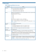
A Utilities SAS disk setup Using the saupdate command The saupdate command is used to query or change the mode of the Smart Array P410i and Smart Array P411 controllers to HBA or RAID. Querying or changing modes is not supported for other controllers. The newly added commands to SAUPDATE are: • Get Mode • Set Mode Get mode This command displays the current mode of the controllers. Syntax saupdate get_mode can be any one of the following strings.
Set mode IMPORTANT: If you are using HBA mode, do not install any disk that has previously been a part of a RAID volume into the system. Set mode is used to change the mode of the controller. If the controller is already in the required mode the following message appears: The controller at seg:bus:dev:funcis already in HBA|RAID mode. Syntax saupdate set mode [-f] can be any one of the strings listed in Table 46 (page 145).
To change the mode of the controller use saupdate set_mode [-f]. NOTE: A system reset or a reconnect-r is required after changing from HBA to RAID mode. An alert message about the possible data loss is displayed when a mode change command is issued. A confirmation is required before the actual mode change is made. This ensures unintentional change of mode does not happen.
3. 4. 5. 6. 7. To select the Raid Configurations section and select the RAID type for the logical drive, press Tab. To select the Spare section and assign spare disks, as needed, press Tab. To create the logical drive, press Enter. A summary of your choices appears. To save the configuration, press F8. If the function keys are disabled, press Esc and then press 8. To acknowledge that the configuration was saved and return to the ORCA Main Menu, press Enter.
3. Enter the license key and press Enter. 4. Verify your license key. See “Viewing RAID advanced pack license keys” (page 149). Viewing RAID advanced pack license keys 1. 2. 3. At the ORCA main menu, select Manage License Keys. Select View License Key(s). All advanced pack license keys are displayed. Press Esc to return to the License Keys Menu. UEFI UEFI is an OS and platform-independent boot and preboot interface.
Table 47 UEFI shell commands 150 UEFI shell command Definition ? Displays the UEFI Shell command list or verbose command help alias Displays, creates, or deletes UEFI Shell aliases attrib Displays or changes the attributes of files or directories autoboot Set/View autoboot timeout and retries bcfg Display/Modify the driver/boot configuration boottest Turn specific speedyboot bits on or off cd Displays or changes the current directory cls Clears standard output and optionally changes backg
Table 47 UEFI shell commands (continued) UEFI shell command Definition help Displays the UEFI Shell command list or verbose command help hexedit Full screen hex editor if Executes commands in specified conditions ifconfig Modify the default IP address of UEFI network stack info Display hardware information input Take user input and place in UEFI variable ioconfig Deconfigure/Reconfigure IO components or settings lanaddress Display LAN devices lanboot LAN boot load Loads and optionally c
Table 47 UEFI shell commands (continued) UEFI shell command Definition stall Stalls the processor for the specified number of microseconds tapeboot Boot from tape tftp Perform TFTP operation time Displays or changes the current system time timezone Displays or sets time zone information touch Updates filename timestamp with current system date and time type Displays file contents unload Unloads a UEFI driver ver Displays UEFI Firmware version information vol Displays or changes a file s
NOTE: Everything after "Scsi" or "SAS" in the output can vary because each SAS drive/partition is unique Using the boot maintenance manager This menu enables you to change various boot options. The Boot Maintenance Manager Contains the following submenus: • Boot Options • Driver Options • Console Options • Boot From File • Set Boot Next Value • Set Time Out Value • Reset System NOTE: Use the dmpstore command to back up these settings.
Add boot option Use this option to add items to the Boot Options list. To add a boot option: 1. Select a boot device type.
2. Use the File Explorer menu to locate the correct boot device. NOTE: File Explorer loads with the appropriate devices for the selected boot device. Delete boot option Use this option to remove boot options from the Boot Options list. NOTE: This does not delete any files, applications or drivers from your server. To remove items from the boot list: 1. 2. Press spacebar to toggle the checkbox for each boot options that you want to delete.
To change the boot order: 1. Select an item on the boot order list. 2. Using the + and - keys, move the selection to the desired position in the book order list. 3. 4. Press Enter when the item is in the desired position. Select Commit Changes and Exit to save the new settings and return to the Boot Maintenance Manager.
1. Select Add Driver Using File. 2. Use the File Explorer menu to locate the correct driver. Delete driver option Use this option to remove driver options. NOTE: This does not delete any files, applications or drivers from your server. To remove driver options: 1. Press spacebar to toggle the checkbox for each driver that you want to delete. 2. Select Commit Changes and Exit to save the new settings and return to the Boot Maintenance Manager.
4. Select Commit Changes and Exit to save the new settings and return to the Boot Maintenance Manager. Console options The Console Options menu is not currently supported. Use the conconfig command from the UEFI Shell to set console options. Boot from file Use this option to manually run a specific application or driver. NOTE: This option boots the selected application or driver one time only. When you exit the application, you return to this menu. 1. Select a boot device type. 2.
Set time out value Use this option to set the amount of time the server pauses before attempting to launch the first item in the Boot Options list. Interrupting the timeout during the countdown stops the Boot Manager from loading any boot options automatically. If there is no countdown, boot options must be selected manually. To set the auto boot timeout value, in seconds, select Set Timeout Value and enter the desired value. Reset system Use this option to perform a system reset.
Access to the iLO MP can be restricted by user accounts. User accounts are password protected and provide a specific level of access to the server and MP commands. For more information regarding the iLO MP, see the HP Integrity iLO 3 Operations Guide. http://www.hp.
Index Symbols 1+1 capability power supplies, 27, 49 A AC power Data Center server, 27 input, 27 access panel removal, 106 air baffle System battery, 129 autoboot, 38 B bezel cover attaching, 24 removal, 108 boot option add, 154 change boot order, 155 delete, 155 Set Boot Next Value, 158 boot option maintenance manager menu, 153 boot options list, 38 add HP-UX, 39 add OpenVMS, 42 booting from file, 158 HP-UX (LVM maintenance mode), 41 HP-UX (UEFI boot manager), 40 HP-UX (UEFI Shell), 40 HP-UX in single-ser
field replaceable units list, 101 firmware types, 97 updates, 34 updating, 97 flash-backed write cache super capacitor removing and replacing, 121 front panel controls, 73 overview, 14 FRU list, 101 full-length expansion board, 53, 120 H half-length expansion board, 53, 119 hard disk drive see SAS disk drive hard drive backplane, 117 hard drive blanks, 111 hard drives Hot-plug SAS hard drive, 111 hardware monitoring, 81 HDD see SAS disk drive heat sink module installing, 59 removing, 124 hot plug disk driv
P parts information overview, 99 PC command, 33, 34 PCI riser cage, 51, 118 pedestal installing the server into, 21 pedestal bottom attaching, 22 removal, 109 pedestal feet attaching, 27 removal, 103, 107 pedestal side removal, 105 pedestal sides attaching, 25 pedestal top attaching, 22 removal, 109 phone supprt, 140 power, 113 see also power supply full state, overview, 33 off state, overview, 33 overview, 113 PR command, 33 sources, 27 standby, 28 standby state, overview, 33 states, 28, 33 power button fu
system battery, 129 system board removing and replacing, 134 system boot options, 38 system build-up procedures, 83 system event logs overview, 83 system fans see fans system health LED definition, 74 Systems Insight Display LEDs Systems Insight Display, 130 T Telco racks Preparation procedures, 102 telco racks Remove the server from the rack, 106 thumbscrew locations, 105, 108 TPM (Trusted Platform Module), 64 troubleshooting basic and advanced information, 69 boot process, 96 console issues , 87 cooling