
HP Integrity rx2800 i2 Server User Service Guide

1. Power LED on front panel glows steady amber when one or two bulk power supplies are
plugged into nominal AC voltage and the +3.3 VDC housekeeping voltage comes on and
stays on whenever AC power is present.
2. The iLO 3 MP, Flash memory, and server intrusion circuits are reset after the +3.3 V DC
housekeeping voltage stabilizes.
3. The iLO 3 MP monitors the power button on the front panel.
4. When the power button is pressed, iLO 3 signals the bulk power supplies to fully power up.
5. The +12 V DC rail comes up and all of the cooling fans and the various Voltage Regulators
come up sequentially.
6. The iLO 3 MP signals when the server is ready to come out of reset (clocks are programmed
and stable, etc.).
7. The server is brought out of reset, and begins the boot process.
Power LED button
The front panel system power LED indicates the status of system power. The LED is incorporated
inside the power button itself.
The power button has a momentary switch (as opposed to a latching switch) that is recessed or
covered to prevent accidental activation or deactivation.
If the OS is up, pressing the power button for less than four seconds results in a graceful shutdown
of the operating system and a subsequent removal of system power. Pressing the power button for
greater than four seconds results in a hard shutdown (system power removed). While the server is
booting (before the system has passed UEFI_EXIT_BOOT_SERVICES), the iLO MP immediately
powers the server off on a button press, since there is no concept of soft shutdown in this state.
In the event that the OS is absent or hung, or that the manageability subsystem (specifically the
iLO MP) in the server is not responding, a greater than four second press of the power button is
required to power off the system (a less than four second press on the power button has no effect).
To ensure that the system powers up in a deterministic fashion, the power button must be masked
for four seconds after a power-down.
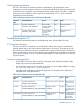
Table 34 Power LED States
LED colorFlash rateDefinition
LED OffNo AC power to the system
GreenSteadySystem power is turned on
AmberSteadySystem is shut down, but AC and housekeeping (standby) power are
active.
For high availability and safety reasons, this LED runs off the power rails, rather than under firmware
control.
Troubleshooting the cooling subsystem
The fans located within the server provide N+1 redundancy for the server using six identical dual
fan assembly CRUs. In turn, each dual fan assembly CRU provides additional N+1 redundancy
for the fan cooling zone it controls. Each dual fan assembly CRU is identified by the server as fans
1 through 6 both for logging purposes and for fault identification on the diagnostic LED panel.
Cooling fan CRU failures are identified visually by a single green LED on the dual fan assembly
CRU that is turned on when one or both of the fans fail; logged as an IPMI event by fan sensor
logic; and identified as a fan assembly CRU failure by iLO 3 turning on the appropriate LEDs on
the System Insight Display panel.
92 Troubleshooting