HP Integrity rx2800 i4 Server Installation Guide Abstract This document contains specific information that is intended for users of this HP product. This document provides system information, server specifications, and installation procedures for the HP Integrity rx2800 i4 Server.
© Copyright 2012 Hewlett-Packard Development Company, L. P. Legal notices The information contained herein is subject to change without notice. The only warranties for HP products and services are set forth in the express warranty statements accompanying such products and services. Nothing herein should be construed as constituting an additional warranty. HP shall not be liable for technical or editorial errors or omissions contained herein.
Contents 1 Installing the server.....................................................................................5 Safety information....................................................................................................................5 Preventing electrostatic discharge................................................................................................5 Installation sequence and checklist..........................................................................................
Customer self repair................................................................................................................24 Standard terms, abbreviations and acronyms..................................................25 Index.........................................................................................................
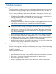
1 Installing the server Safety information Follow the instructions carefully to prevent injury and equipment damage when performing removal and replacement procedures. Voltage might be present within the server. Many assemblies are sensitive to damage by ESD.
Installation sequence and checklist Step Description 1 Perform site preparation (see The HP Integrity rx2800 i4 Server User Service Guide). 2 Install the server into a rack or pedestal. 3 Connect cables to the server. Completed a. Connect the AC input power cable. b. Connect LAN core I/O cable. c. Connect the iLO 3 MP LAN cable. 4 Connect and set up the console for access. 5 Power on the server. 6 From iLO MP, access UEFI. 7 Boot the operating system.
3. Repeat these steps for the rail on the other side of the server. Figure 1 Removing the rails from the server Attaching the pedestal kit top and bottom IMPORTANT: In this document the server top, bottom, right and left refer to the server as faced from the front with the server in a horizontal orientation. The pedestal kit components are referred to by the final position with the server in a vertical orientation. For example, the pedestal kit bottom attaches to the server right side.
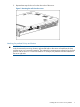
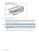
Figure 2 Front of server 1 2 Server top/pedestal right Server left/pedestal top 3 4 Server bottom/pedestal left Server right/pedestal bottom The pedestal kit bottom attaches to the right side of the server when the server is in the horizontal position. The pedestal kit top attaches to the left side of the server when in the server is in the horizontal position. The pedestal bottom can be distinguished from the pedestal top by the pedestal feet slots.
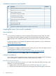
2. 3. Hold the pedestal component flush against the server. Slide the pedestal component forward until it locks into place. Figure 3 Installing the pedestal bottom piece 4. Stand the server up on the bottom piece of the pedestal kit that was just installed so the server is in the vertical position. CAUTION: The server is heavy. Be careful when lifting it to the vertical position. Without the feet installed, the server might tip over easily.
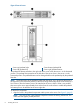
Figure 4 Attaching the bezel cover Attaching the pedestal kit side pieces The pedestal kit right side piece attaches to the top of the server. The top cover of the server might have ventilation holes in it to enable proper air flow and cooling. The right side piece of the pedestal kit also has ventilation holes in it to enable the proper cooling and air flow. Follow these steps to attach the pedestal kit right side piece.
Figure 5 Attaching the pedestal kit side piece 3. Secure the pedestal side by hand tightening the captive thumb screws on the rear of the server.
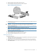
Repeat these steps to install the left side piece. Attaching the pedestal feet The pedestal feet slide into the slots on the pedestal bottom, two on each side. The feet are all the same and can be mounted in any slot on the bottom piece of the pedestal kit. Figure 7 Attaching the feet Connecting server cables AC input power The server can receive AC input from two different AC power sources. The power receptacles are located at the rear of the server.
Power states The server has the following power states: • Standby power • Full power • Off Table 2 Power states Power states Power cable plugged into receptacle? Power activated through the iLO 3 PC command; or front panel power button activated? Standby DC DC voltage voltage applied? applied? Standby power Yes No Yes No Full power Yes Yes Yes Yes Off No No No No CAUTION: If the server is expected to remain in standby mode for more than 30 minutes, AC power should be completely remo
Setup checklist Use the checklist in Table 3 while setting up the Integrity iLO 3. Table 3 Setup checklist Step Action Procedure Status Standard setup 1 Preparation 1. Determine an access method to select and connect the cables. 2. Determine a LAN configuration method and assign an IP address if necessary.
NOTE: The prompt might take several minutes to appear, and the period that you can press Ctrl-C is very short. For typical boots, HP recommends that you let the prompt time out. After selecting an option, the boot proceeds. NOTE: 3. If no option is selected, the boot proceeds after a few seconds.
To view boot options, or launch a specific boot option, press B to launch the Boot Manager. To configure specific devices, press D to launch the Device Manager. This is an advanced feature and must only be performed when directed. To perform maintenance on the system such as adding, deleting, or reordering boot options, press M to launch the Boot Maintenance Manager.
To perform more advanced operations, press S to launch the UEFI Shell. To view the iLO LAN configuration, press I to launch the iLO Setup Tool. Saving UEFI configuration settings You can configure other UEFI settings at this time. For more UEFI configuration options, see the HP Integrity rx2800 i4 Server User Service Guide.
Powering on and powering off the server Power states The server has the following power states: • Standby power • Full power • Off For details about server power states, see Table 2 (page 13). NOTE: If the power restore feature is set to Always On through the iLO 3 MP PR command, the server automatically powers on to the full power state when the power cord is plugged in to the server.
6. Boot the operating system. For more information, see the operating system documentation. Powering on the server manually NOTE: If the power restore feature is set to Always On through the iLO 3 MP PR command, the server automatically powers on to the full power state when the power cord is plugged in to the server. 1. 2. 3. Plug all power cables into the receptacles on the rear panel of the server. Press the power button to start the server. Start the operating system.
agent for remote installations. After the installation is complete, HP Smart Update Manager also removes all remote files associated with the installation.
2 Support and other resources Contacting HP Information to collect before you contact HP NOTE: HP recommends that you record any changes that you make to your system, as well as how the changes affect system behavior. 1. 2. 3.
HP contact information For the name of the nearest HP authorized reseller: • See the Contact HP worldwide (in English) webpage (http://www.hp.com/country/us/en/ wwcontact.html). For HP technical support: • • In the United States, for contact options see the Contact HP United States webpage (http:// welcome.hp.com/country/us/en/contact_us.html). To contact HP by phone: ◦ Call 1-800-HP-INVENT (1-800-474-6836). This service is available 24 hours a day, 7 days a week.
proactive notification, but do not need proactive service delivery and integration with a management platform. • HP Insight Remote Support Advanced: This software provides comprehensive remote monitoring and proactive service support for nearly all HP servers, storage, network, and SAN environments, plus selected non-HP servers that have a support obligation with HP. It is integrated with HP Systems Insight Manager.
ComputerOut Text displayed by the computer. UserInput Commands and other text that you type. Command A command name or qualified command phrase. Option An available option. Screen Output Example of computer screen output. [ ] The contents are optional in formats and command descriptions. If the contents are a list separated by |, you must select one of the items. { } The contents are required in formats and command descriptions.
Standard terms, abbreviations and acronyms CRU Customer Replaceable Unit. DHCP Dynamic Host Configuration Protocol. ESD Electrostatic discharge. FRU Field Replaceable Unit. Hot-pluggable A component that can be removed from the server while the server remains operational, but software intervention is required prior to removing the component. Hot-pluggable components are signified with red touch points.
Index Symbols P 1+1 capability power supplies, 12 PC command, 18, 19 pedestal installing the server into, 6 pedestal bottom attaching, 7 pedestal feet attaching, 12 pedestal sides attaching, 10 pedestal top attaching, 7 phone supprt, 22 power full state, overview, 18 off state, overview, 18 PR command, 18 sources, 12 standby, 13 standby state, overview, 18 states, 13, 18 power reset command see PR command powering off the server, 19 manually, 19 using the iLO 3 MP PC command, 19 powering on the server, 1
accessing from iLO MP, 14 Front Page, 15 27