HP Integrity rx3600 Server Installation Guide HP Part Number: AB463-9001E Published: November 2011 Edition: 5
© Copyright 2006, 2011 Hewlett-Packard Development Company, L.P Legal Notices The information contained herein is subject to change without notice. The only warranties for HP products and services are set forth in the express warranty statements accompanying such products and services. Nothing herein should be construed as constituting an additional warranty. HP shall not be liable for technical or editorial errors or omissions contained herein.
Contents About This Document.....................................................................................6 Intended Audience....................................................................................................................6 New and Changed Information in This Edition..............................................................................6 Publishing History.....................................................................................................................
Replacing the Processor Board Assembly..........................................................................29 Installing a Dual-Core Processor...........................................................................................29 Processor Load Order....................................................................................................30 Required Tools..............................................................................................................
Viewing the VPD Information for EFI Driver and RISC Firmware.......................................52 EFI Commands.............................................................................................................52 DRVCFG Utility.............................................................................................................52 Starting the DRVCFG Utility.......................................................................................52 Using the DRVCFG Utility...................
About This Document This document describes how to unpack the HP Integrity rx3600 server, install additional components, start a server console session, power on the server, and boot the operating system. The document publication date and part number indicate the document’s current edition. The publication date changes when a new edition is published. Minor changes may be made without changing the publication date. The document part number will change when extensive changes are made.
Ctrl+x A key sequence. A sequence such as Ctrl+x indicates that you must hold down the key labeled Ctrl while you press another key or mouse button. ENVIRONMENT VARIABLE The name of an environment variable, for example, PATH. ERROR NAME The name of an error, usually returned in the errno variable. Key The name of a keyboard key. Return and Enter both refer to the same key. Term The defined use of an important word or phrase. User input Commands and other text that you type.
You can find the entire Prentice Hall Professional Series on HP at: http://www.informit.com/imprint/series_detail.
1 Installing the System This chapter covers the procedures for installing the HP Integrity rx3600 server.
• If installing an internal assembly, wear an antistatic wrist strap and use a grounding mat, such as those included in the Electrically Conductive Field Service Grounding Kit (HP 9300-1155). • Handle accessory boards and components by the edges only. Do not touch any metal-edge connectors or any electrical components on accessory boards. Installation Sequence and Checklist Table 2 lists the server installation steps. Follow these steps in sequence to install the server.
Inspecting the Shipping Containers for Damage HP shipping containers protect their contents under normal shipping conditions. After the equipment arrives, carefully inspect each carton for signs of shipping damage. Shipping damage constitutes moderate to severe damage, such as punctures in the corrugated carton, crushed boxes, or large dents. Normal wear or slight damage to the carton is not considered shipping damage.
Installing Additional Components This section describes how to install components into the server that are not factory integrated. Most servers are pre-configured with all components installed prior to shipping from the HP factory. If you do not have additional components to install, go on to “Installing the Server into a Rack or Pedestal Mount” (page 32). Removing and Replacing the Top Cover This section describes how to remove and replace the server top cover.
Removing and Replacing the Memory Carrier Assembly Cover This section describes how to remove and replace the memory carrier cover. Removing the Memory Carrier Assembly Cover To remove the memory carrier assembly cover, follow these steps: 1. Unlock the cover release lever. Turn the cam 90 degrees counterclockwise. 2. Pull up on the cover release lever to disengage the top cover and memory carrier assembly cover from the chassis (Figure 1). 3.
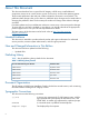
Power Supply Loading Guidelines The supported configuration of the server requires a minimum of one power supply installed in either slot P0 or slot P1. You can install a second, optional hot-swappable power supply to provide 1+1 capability. The left side (viewed from the rear of the chassis) hot-swappable power supply is identified as P0, and the second hot-swappable power supply is identified as P1 (Figure 3).
Figure 3 Installing a Hot-Swappable Power Supply Removing and Replacing Hot-Swappable Disk Drive Fillers There are disk drive fillers installed on the front of the server for all slots that do not contain a disk drive. IMPORTANT: disk drive. For cooling purposes, always leave disk drive fillers in slots that do not contain a Removing a Hot-Swappable Disk Drive Filler To remove a hot-swappable disk drive filler, follow these steps: 1.
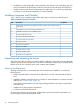
1. 2. Orient the disk drive filler so that the release tab is on the left side of the filler and the airflow holes are on the right side of the filler. Insert the filler into the slot guides, and slide the filler into the slot until it clicks into place and is fully seated. Installing a Hot-Pluggable Disk Drive There are eight hot-pluggable disk drives located in the front of the server. You can replace the hot-pluggable disk drives using the procedures in this section when the server power is on or off.
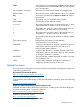
Figure 4 Installing a Hot-Pluggable Disk Drive Figure 5 Disk Drive Slot IDs Installing a PCI/PCI-X/PCIe Card Figure 6 shows the PCI/PCI-X/PCIe slot identification and card divider locations. NOTE: Slots one through eight are full-length; slots nine and ten are short-length.
Figure 6 PCI/PCI-X Slot Identification and Card Divider Locations 1 2 3 4 Slot Slot Slot Slot 1 2 3 4 5 6 7 8 Slot Slot Slot Slot 5 6 7 8 9 10 11 12 Slot 9 Slot 10 Core I/O Board Slot PCI/PCI-X/PXIe Card Dividers PCI/PCI-X/PCIe Configurations PCI/PCI-X/PCIe slots are numbered one through ten in the server (Figure 6).
NOTE: Shared slots have card compatibility restrictions. If one of the shared slots is occupied, the card added to the second slot is limited by the configuration of the occupied slot. If the new card has a slower capability than the current bus configuration, it fails. If the new card has a faster capability than the current bus configuration, it only runs at the slower bus mode and frequency of the current bus configuration. The following are common configuration scenarios for cards that use shared slots.
Table 3 PCI/PCI-X Card Slot Frequency and Bus Mode Compatibility for Shared Slots1 Current PCI Bus Mode and Frequency for the Card in a Shared Slot Cards to be Installed PCI 33 PCI 66 PCI-X 66 PCI-X 133 PCI-X 266 PCI 33 MHz Compatible2 Compatible2 Compatible2 Compatible2 Compatible2 New card New card running New card running New card running running at PCI 33 at PCI 33 at PCI 33 at PCI 33 PCI 66 MHz PCI-X 66 MHz 1 2 3 4 Incompatible frequency3 Compatible2 Incompatible frequency3 Incompat
Removing and Replacing the Memory Carrier Assembly The memory carrier assembly encloses the system DIMMs. There are two different memory carrier assemblies available for the server: • 8-DIMM memory carrier assembly • 24-DIMM memory carrier assembly The 8- and 24-DIMM memory carrier assemblies have two sides, 0 and 1, each of which contain a memory board. System DIMMs seat onto the memory boards. Table 4 lists the supported memory carrier assembly configurations.
Figure 7 Removing and Replacing the Memory Carrier Assembly Replacing the Memory Carrier Assembly CAUTION: Ensure that the processor board assembly is fully seated before you replace the memory carrier assembly. The processor board assembly access door must be flush with the front bezel. To replace the memory carrier assembly, follow these steps: 1. Ensure the extraction handles are positioned in the outward, unlocked position. 2.
Installing System Memory DIMMs System memory or DIMMs are located on a pair of memory boards inside the memory carrier assembly. WARNING! Ensure that the system is powered off and all power sources have been disconnected from the server prior to performing this procedure. Voltages are present at various locations within the server whenever an AC power source is connected. This voltage is present even when the main power switch is in the off position.
• 4 GB • 8 GB Table 5 lists the supported memory configurations for the server.
Figure 9 8-DIMM Memory Carrier Board Slot IDs 24-DIMM Memory Carrier Load Order The 24-DIMM memory carrier has two sides, labeled side 0 and side 1, each of which contains a memory carrier board. The 24-DIMM memory carrier can contain up to six quads of memory. DIMM quads are loaded in order of size from largest to smallest capacity. DIMM quads are loaded in a certain way to balance the memory capacity between the two sides of the memory carrier, starting with side 0.
Memory Loading Rules and Guidelines Use the following rules and guidelines when installing memory: • Install DIMMs in pairs for the 8-DIMM memory carrier and quads in the 24 DIMM memory carrier. • Ensure that all DIMMs within a pair or quad are identical. • Install pairs or quads in order of capacity from largest to smallest. For example, install all 2 GB quads before 1 GB or smaller quads, and install all 1 GB quads before 512 MB quads.
Installing Memory IMPORTANT: You must pull the AC power plugs on the server every time you modify the DIMMs. If you do not pull the AC power plugs, the system does not display the correct DIMM information. To install memory, follow these steps: 1. Unlatch the cover release lever on the top cover and remove the memory carrier assembly cover. See “Removing the Memory Carrier Assembly Cover” (page 13).
6. Install the DIMMs (Figure 11). a. Align the DIMM with the slot located on the memory board, and align the key in the connector with the notch in the DIMM. b. Push on each end of the DIMM firmly and evenly until it seats into the slot. c. Ensure that the extraction levers are in the fully closed position. Figure 11 Inserting a DIMM into the Memory Board Connector 7. Replace the memory carrier assembly side cover. a.
1. Unlatch the cover release lever on the top cover and remove the memory carrier assembly cover. See “Removing the Memory Carrier Assembly Cover” (page 13). NOTE: You do not need to fully remove the top cover to service this component; however, the top cover release lever must be open. You must remove the memory carrier because it attaches directly to the processor board. 2. 3. Remove the memory carrier assembly. See “Removing the Memory Carrier Assembly” (page 21).
The server can contain one or two dual-core processors that provide the following configuration options: • 1P/2C (One processor/two cores) • 2P/4C (Two processors/four cores) WARNING! Ensure that the system is powered off and all power sources have been disconnected from the server prior to performing this procedure. Voltages are present at various locations within the server whenever an AC power source is connected. This voltage is present even when the main power switch is in the off position.
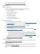
4. Open the processor cage (Figure 13). a. Grasp the processor cage handle and rotate the handle upward. b. Use the handle to rotate the cage closure 90 degrees toward the front of the assembly until it stops. IMPORTANT: Ensure the processor slot is entirely exposed. The processor must clear the cage closure for proper installation. 5. 6. 7. 8. Locate the appropriate processor slot (Module 0 or Module 1) to install the processor into (Figure 13).
17. Replace the memory carrier assembly cover and latch the top cover release lever closed. See “Replacing the Memory Carrier Assembly Cover” (page 13). Figure 13 Processor Board Assembly (Front View) Figure 14 shows the power connectors, the processor lock / unlock mechanism location and the alignment holes. One processor is installed in the illustration.
HP Rack HP servers that are installed into racks are shipped with equipment mounting slides. An installation guide comes with each set of slides: HP 3-7U Quick Deploy Rail System Installation Instructions for HP Products. Follow the steps in this installation guide to determine where and how to install the server into the rack. The following are additional instructions for installing the HP Integrity rx3600 server into the rack: 1.
Power States The server has three power states: • standby power • full power • off To get to standby power state plug the power cord into the appropriate receptacle on the rear of the chassis. The front panel Power button is not turned on. Full power occurs when the power cord is plugged into the appropriate receptacle and either the power is activated through the iLO 2 MP PC command, or the Power button is activated. In the off state, the power cords are not plugged in.
2. Attach the other end of the strap to the power cord (Figure 16). Figure 16 Fastening the Power Supply Applying Standby Power to the Server To apply standby power to the server, follow these steps: IMPORTANT: 1. 1. 2. If the server has one BPS, plug the power cable into the receptacle labeled PWR Locate the appropriate receptacle on the rear of the chassis. Plug the power cord into the receptacle.
Figure 17 Rear Panel LAN Ports To enable general network connectivity for the server, follow these steps: 1. Obtain valid IP addresses for each LAN port you plan to activate. 2. Connect the LAN cable from an available LAN port to a live connection on the network. Console Setup Setting up the console involves the following: 1. Determining the physical access method to connect cables. There are two physical connections to the Integrity iLO 2: 2.
Table 10 Elements Required to Start a Console Session Console Element Description AC power (standby power) The server must have AC power to provide console functionality. See “Applying Standby Power to the Server” (page 35). Server hardware components Includes the iLO 2 MP and console cable connectors. Console cable Links the server console to the console device. Console device Provides display and input functionality using components such as monitors, keyboards, and mouse devices.
Figure 18 Console Setup Flowchart Preparation There are several tasks to perform before you can configure the iLO 2 MP LAN. • Determine the physical access method to select and connect cables. • Determine the iLO 2 MP LAN configuration method and assign an IP address if necessary. Determining the Physical iLO 2 MP Access Method Before you can access the iLO 2 MP, you must first determine the correct physical connection method. The iLO 2 MP has a separate LAN port from the system LAN port.
Figure 19 Server Rear Ports 1 2 3 4 iLO 2 MP RS-232 Serial Port (DB-9F to DB-9F cable) Connected to emulation terminal device (PC, laptop, or ASCII terminal) USB 2.0 Ports (any USB device) BMC Heartbeat MP Heartbeat 5 VGA Port 9 10 6 (No iLO 2 MP access; EFI only) General Use Serial Port 7 8 11 Link and Activity LED Standby Power MP Self Test (Printers, etc.
Once you have determined the iLO 2 MP access, you must determine how you will configure the iLO 2 MP LAN in order to acquire an IP address. There are three methods available. • DHCP/DNS • ARP Ping • RS-232 serial port Table 13 provides all the possible scenarios to consider. Use this table to help you select the appropriate LAN configuration method to obtain an IP address.
1. Obtain the factory-set host name from the iLO 2 MP Media Access Protocol (MAC) address label on the server. The default host name is 14 characters long, consisting of the letters mp followed by the 12 characters of the MAC address as in this example: mp0014c29c064f This address is assigned to the iLO 2 MP core IO board. The core IO board has a unique MAC address that identifies the hardware on the network.
Table 14 ARP Ping Commands ARP Command Description arp -s This command assigns the IP address to the iLO 2 MP MAC address. This ARP table entry maps the MAC address of the iLO 2 MP LAN interface to the static IP address designated for that interface. ping This command tests network connections. It verifies the iLO 2 MP LAN port is configured with the appropriate IP address.
IMPORTANT: Ensure you have a console connection through the RS-232 serial port or a network connection through the LAN to access the iLO 2 MP and use the LC command. To assign a static IP address using the LC command, follow these steps: 1. Ensure the emulation software device is properly configured. The terminal emulation device runs software that interfaces with the server. The software emulates console output as it would appear on an ASCII terminal screen and displays it on a console device screen.
2. Log in using the default the iLO 2 user name and password (Admin/Admin). TIP: For security reasons, HP strongly recommends you modify the default settings during the initial login session. See “Modifying User Accounts and Default Password” (page 44).
3. To setup user accounts: a. Access the MP Main Menu. b. Enter CM at the MP> prompt. c. Enter UC at the MP:CM> prompt and follow the prompts to modify user accounts. Setting Up Security For greater security and reliability, HP generally recommends that iLO 2 MP management traffic be on a separate dedicated management network and that only administrators be granted access to that network.
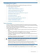
To interact with iLO 2 through the web GUI, follow these steps: 1. Open a web browser and enter the host name or the IP address for the iLO 2 MP. 2. Log in using your user account name and password at the login page. (Figure 20). Figure 20 Web Login Page 3. Click Sign In. The Status Summary page (Figure 21) displays after login. Figure 21 Status Summary Page 1. 2. 46 Select the web interface functions by clicking the Function tabs at the top of the page.
3. Click the Remote Console tab. The remote console provides the following options to access the console: • A serial console that behaves similarly to the TUI of the following section • The virtual KVM console Help The iLO 2 web interface has a robust help system. To launch iLO 2 help, click the Help tab in the Display screen or click the ? at the top right corner of each page to display help about that page.
Powering On and Powering Off the Server This section provides information and procedures for powering off and powering on the server. Power States The server has three power states: Standby power Plug the power cord into the appropriate receptacle on the rear of the chassis; the front panel Power button is not turned on. Full power Full power occurs when you plug the power cord into the appropriate receptacle, and either activate the power using the iLO 2 MP PC command, or press the Power button.
Figure 22 rx3600 Power Button 3. Start the operating system. For more information see the operating system documentation. Powering Off the Server Power off the server using the following methods: • iLO 2 MP PC command • Power button Powering Off the Server Using the iLO 2 MP To power off the server using the iLO 2 MP, follow these steps: 1. Gracefully shut down the operating system. For more information see the operating system documentation. 2. Initiate a console session and access the MP Main Menu.
Integrated RAID Use Integrated RAID (IR) where either storage capacity, redundancy, or both of a RAID configuration are required. Two components of IR are: • Integrated Mirror (IM) • Global Hot Spare Integrated Mirror The advantage of an IM is there is always a mirrored copy of the data. An IM provides data protection for the system boot volume to safeguard critical information such as the operating system on servers and high performance workstations.
3. To determine the current version of the firmware, follow these steps. a. At the EFI Shell, enter mptutil from the directory that contains mptutil.efi. The following example indicates that the EFI Serial Attached SCSI card utility version is 1.01.12.00: fs0:\EFI\HP\TOOLS\NETWORK> mptutil MPTUTIL-1.01.12.00 Vendor Device Choice ID ID Bus Device ------ ------ ------ --- -----0 1000h 0054h 14h 01h LSI Logic SAS1068 Host Adapter 1 - Refresh b. 4. 5. Press Enter.
Answer The firmware you just flashed on the HBA does not run until a diagnostic reset occurs. If you exit the utility and reenter it, the version string is updated. Question This image does not contain a valid nvdata when I try to flash the firmware, why? Answer You are expected to concatenate a proper nvdata image on to the firmware. MPTUTIL keeps you from flashing an image without one. To concatenate nvdata and firmware you need to run the mptutil -o -d 64it__l.fw,sas106x.dat,output.fw command. .
+/- Change Item - Items with values in [ ] brackets are modifiable. Numeric keypad + and numeric keypad - (minus) update a modifiable field to its next relative value. Esc Abort/Exit - Escape aborts the current context operation and/or exits the current screen. User confirmation is solicited as required if changes have been made by user. If you are using a serial console, pressing Esc causes a delay of several seconds before it takes effect. This is normal system behavior and is not an error.
PCI Dev Indicates the PCI Device assigned by the system BIOS to an adapter (range 0x00 - 0x1F, 0 - 31 decimal) PCI Fnc Indicates the PCI Function assigned by the system BIOS to an adapter (range 0x00 - 0x7, 0 - 7 decimal) FW Revision Displays the Fusion MPT firmware version and type (IR or IT) Status Indicates whether the adapter is or is not eligible for software control (enabled, disabled or error) Enabled Indicates the EFI Driver is either currently controlling the adapter, or will attempt to cont
FW Revision Displays the MPT firmware version and type in the format (x.xx.xx.xx- yy), where x.xx.xx.xx refers to the FW version and yy refers to the type. The currently supported type is IR.l). SAS Address Displays the SAS Address assigned to this adapter. FW Revision Displays the Fusion MPT firmware version and type (IR or IT) Status Indicates whether an adapter is eligible for configuration utility software control or is reserved for control by other software (Enabled, Disabled or Error).
Select New Array Type Screen The Select New Array Type screen enables you to view an existing array or create an Integrated Mirror array of two disks, plus an optional hot spare. • To go to the Create New Array screen, select Create IM Volume. • To go to the View Array screen, select View an Existing Array. Create New Array Screen The Create New Array screen enables you to create a new array.
Missing Disk is not responding. Failed Disk has failed. Initalizing Disk is initializing. CfgOffln Disk is offline at host's request. User Fail Disk is marked failed at host's request. Offline Disk is offline for some other reason. Inactive Disk has been set inactive. Not Syncd Data on disk is not synchronized with the rest of the array. Primary Disk is the primary disk for a 2 disk mirror and is OK. Secondary Disk is the secondary disk for a 2 disk mirror and is OK.
RAID Disk Hot Spr Drive Status 58 Installing the System Specifies the devices (disks) that make up an IM array. If RAID Disk is Yes, the device is part of an IM array, if No, the device is not part of an IM array. This field is grayed out under the following conditions: • The device does not meet the minimum requirements for use in an IM array. • The device is not large enough to mirror existing data on the primary drive. • This disk has been selected as the hot spare for the IM array.
Pred Fail Indicates whether device SMART is predicting device failure (Yes, No). Size(MB) Indicates the size of the device in megabytes (megabyte = 1024 x 1024 = 1,048,576). If the device is part of a two-disk array, this field reflects the size of the array, not the size of the individual disk. If the device is part of a three or more disk array, this field is the size that the disk makes up within the array.
Exit the SAS Configuration Utility Screen As some changes only take effect when you exit the utility, it is important to always exit the utility properly. To exit the utility, follow these steps: 1. To return to the Adapter List from Adapter Properties, press ESC. 2. To exit the utility from the Adapter List, press ESC. NOTE: A similar exit screen is used when exiting most other screens, and can be used to save settings.
The cfggen command uses a command line interface. Syntax: cfggen NOTE: The program name, controller number, command, and parameters fields must be separated by the ASCII space character. The format of the parameters is command specific. The program return value is returned to the user when the program exits. A value of 0 is returned if the command is successful. Otherwise, a value of 1 is returned.
SCSI ID values for disks to use in the volume. The cfggen utility automatically uses the first disks it finds that are usable in the IM volume. Firmware and hardware limitations for the family of controllers limit the number of configurations that are possible. Syntax cfggen auto [qsync] [noprompt] Parameters Volume type for the volume to be created. Valid value is IM. Size of the RAID volume in Mbytes or “MAX” for the maximum size available.
4. 5. 6. Update the controller firmware (see “SAUPDATE Utility” (page 64)). When the firmware update process is complete, the server reboots and runs through a POST procedure. This POST procedure halts briefly during controller initialization and prompts you to open ORCA (Option ROM Configuration for Arrays). Open ORCA. See “Configuring the Array” (page 68). • If using a headless console, press Esc+8. • Otherwise, press F8. Configure the logical boot drive, and exit from ORCA.
SAUPDATE Utility Use saupdate from the EFI Shell to update the firmware image on the HP Smart Array Controller. Command line options are described below. Follow one of these two procedures to run saupdate:. • 1. 2. 3. 4. 5. If you are using saupdate from the Offline Diagnostic CD: Download the firmware and copy it to the EFI partition. The CD containing saupdate.efi must be in the drive before booting the system to allow device mapping. Boot the system to the EFI Shell prompt.
Seg Bus 1 51 1 20 Dev 4 1 Func 0 0 Description HP Smart Array P600 HP Smart Array 5300 Version 1.92 3.54 The identification information from this list is used to designate which controller is to be updated. UPDATE NOTE: The saupdate utility program file (saupdate.efi) must be located in the same file system as the firmware files.
Percentage completed: 100% Activating firmware now, this may take several minutes. Resetting and reinitializing controller. Retrieving firmware version, this may take several minutes. Current controller firmware version is 2.34. ************************************************************ Smart Array Offline Firmware Update Utility Version: 1.04.12.00 (C) Copyright 2004 Hewlett Packard Development Company L.P.
Figure 26 EBSU Welcome Screen 4. 5. Select OK and press Enter to continue. From the main menu, select Maintain Firmware and press Enter. Figure 27 EBSU Main Menu 6. 7. 8. In the Maintain Firmware screen, use the tab key to scroll down to the Device section. Use the down arrow key to scroll down to the Smart Array Controller item in the list. Press Enter to display detailed information about the device.
EBSU displays the firmware update screen for the selected device. • The version number in the first column (ROM Firmware Version) is the one currently installed on your system. • The version number in the second column (ROM Version on Disk) is the one available on your Smart Setup media. Figure 29 EBSU Maintain Firmware Update Screen 9.
same capacity as the smallest drive in the array. The excess capacity of any larger drives is wasted because it is unavailable for data storage. • The probability that an array will experience a drive failure increases with the number of physical drives in the array. If you configure a logical drive with RAID 5, keep the probability of failure low by using no more than 14 physical drives in the array.
2. At the ORCA prompt: • If you are connected using a headless console, press the Esc+8 combination. • Otherwise, press F8. The ORCA Main Menu displays, enabling you to create, view, or delete a logical drive. Figure 30 ORCA Main Menu Creating a Logical Drive Using ORCA To create a logical drive using ORCA, follow these steps: 1. Select Create Logical Drive. The screen displays a list of all available (unconfigured) physical drives and the valid RAID options for the system. 2.
Installation Troubleshooting This section provides basic server troubleshooting information. It is designed to help you diagnose common issues that can occur during server installation. Troubleshooting Methodology The server was tested prior to shipping. Failures encountered during installation can be due to damage that occurred in transit. Reseating connectors can clear problems that result from rough handling.
Table 20 Server Power Button Functions When Server is Off Action Reaction 1-3 seconds System power turns on. Server Does Not Power On The server Power button on the front panel operates differently depending on how long the button is held in, and on what the system is doing when the button is pressed. You must be aware of its uses to properly troubleshoot the system. NOTE: If the server is off, and power is not connected to server power supplies, pressing the Power button has no effect.
DVD Problems DVD problems that occur during installation are usually related to faulty connections. If you are experiencing DVD problems, follow these steps: 1. Remove and reinsert the DVD. 2. Replace the DVD. 3. Remove and reinstall the DVD drive. Check that connectors are fully engaged. 4. Replace the DVD drive. Hard Drive Problems Hard drive problems that occur during installation are usually due to rough handling. The drive may not be correctly seated or may have been damaged in transit.
3. 4. Using the EFI Boot Manager menu, boot to the drive that contains the CD with the updated firmware. Follow the instructions to update the firmware. Enabling the Trusted Platform Module This section provides instructions on how to enable the trusted platform module (TPM). Introduction The TPM is an optional security component which enhances security capabilities for the server if it is running the HP-UX operating system. The TPM is a security chip that is unique to the server.
Index Symbols 24-DIMM memory carrier assembly see memory 8 Internal Port SAS HBA controller, 50 8-DIMM memory carrier assembly see memory A accessing graphic console using VGA, 47 accessing iLO 2 MP with SMASH SM CLP, 47 with TUI - CO command, 47 with vKVM - IRC, 47 with web browser, 45 acu utility, 70 ARP ping commands, 42 B bulk power supplies (BPS), 33 C cable determine physical access method, 38 LAN, 36 power, 35 SAS cable part numbers, 63 cell board, 33 cfggen utility, 60 CM command, 48, 49 command
installing, 27 load order, 24–25 load order, 24-DIMM memory carrier assembly, 25 load order, 8-DIMM memory carrier assembly, 24 supported DIMM sizes, 23 supported memory configurations, 24 memory carrier assembly, removing and replacing, 21 memory extender board see memory carrier assembly mptutil utility, 50 N N+1 capability, 33 O operating system boots or does not boot, 72 orca utility, 69 P password, default, 44 PC command, 48, 49 PCI/PCI-X/PCIe cards card divider locations, 18 configurations, 18 divi