
HP Integrity rx3600 Server User Service Guide

NOTE: The Unit Identifier (UID)/Locator LED has not been included in Table 39, because it is not
used directly for troubleshooting rx3600 servers. However, indirectly, it can provide system
information; for example, when it is blue, the BMC is working.
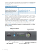
The INIT Button, a momentary switch with pinhole access, used to cause a system INIT or Transfer
of Control (TOC), is not discussed in the following tables either. It is similar to a system reset,
preserving the entire memory image, so that you can obtain a crash dump and receive OS error
information. This button can be used to recover a hung system, and to obtain information useful
for debugging -- it is less harsh than a power reset.
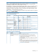
NOTE: In Table 39, LED states indicating error conditions are provided in bold, italic, uppercase
(for example, “
FLASHING AMBER
”).
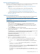
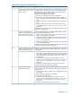
Table 39 lists the front panel LED states.
Table 39 Front Panel LED States
Basic Entry Class Troubleshooting Table
Step Number
System PowerExternal HealthInternal HealthSystem Health
1 in Table 40OffOffOffOff
2a in Table 40Steady amberOffOffOff
2b/2c in Table 40Steady green
FLASHING
AMBER
Steady
green/off
FLASHING AMBER OR RED
8b in Table 41Steady greenSteady green
FLASHING
AMBER
Off
3a/3b in Table 40Steady greenSteady green
FLASHING
AMBER
FLASHING AMBER OR RED
4a, 4b, 4c, and 4d in Table 40Steady greenSteady greenSteady greenOff
8a in Table 41Steady greenSteady greenSteady greenSteady green/off
5, 6, and 7 in Table 40 and Table 41Steady greenSteady greenSteady greenSteady green
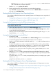
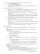
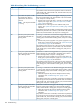
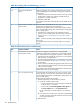
Table 40 lists basic entry class server troubleshooting conditions and actions.
Table 40 Basic Entry Class Troubleshooting
ActionConditionStep
Nothing is logged for this condition.Chassis appears dead -- no front
panel LEDs are on and no fans
are running.
1
1. For new server installations, review the install procedures.
2. Verify that the power cords are connected to both the power
supplies and to the AC receptacles.
3. Verify that acpower, at the proper AC voltage levels, is available
to the receptacles.
4. Check the front panel connector and the cable to the rest of the
system.
5. If the Power button integrated LED on front panel remains off, reseat
the power supplies, replace the power cords, and replace the bulk
power supplies, in that order. See“System Power (BPS and I/O
VRM)” (page 148) for information.
Methodology 127