
HP Integrity rx3600 Server User Service Guide

NOTE: BOOT_START can be determined by LED states on the I/O backplane board.
4. The system health indicator turns green when the firmware leaves exit boot services
and the server starts to boot an OS.
The health LEDs are driven by the BMC; the System Power LED is driven solely by hardware. BMC
code determines the state of the Internal and External Health LEDs. The iLO 2 MP code, examining
incoming events using its event dictionary, determines the state of the System Health LED.
External Health LED
The front panel External Health LED indicates the status of the components that are externally
serviceable. It is used to monitor the power supply. Whenever the external health LED is lit, the
corresponding FRU for the failed component also lights.
NOTE: Failures that cause the External Health LED to light do not cause the Internal Health LED
to light. These two LEDs cover failures of different components.
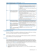
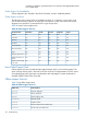
Table 42 lists the External Health LED states
Table 42 External Health LED States
StateFlash RateLED Color
Health good on all external CRUs or system power is off.OffOff
System power is on; externally serviceable components (accessible from front or
back, such as fans and power supplies) are healthy.
SteadyGreen
An externally accessible CRU failed. System is on or in standby mode. Usually, this
is a power supply or fan failure. Check front/back LEDs for failed component.
1 HzAmber
This LED is cleared when all failed externally accessible entities are repaired and report that they
are healthy, or when the system goes into AC/standby power cycle.
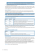
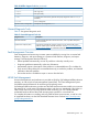
Table 43 lists the iLO 2 MP strings in the Virtual Front Panel (VFP) for the three states of the External
Health LED
Table 43 VFP External Health Description
DescriptionLED State
None.Off
External parts, including fans and power supplies are healthy.Green
A redundant, externally accessible CRU has failed. Check the front/back LEDs.Flashing amber
Internal Health LED
The front panel Internal Health LED indicates the status of the internal system chassis components.
You must open the system to service these components. This LED maintains its state when the system
is in standby mode (system power turned off but AC power still applied to the system).
The amber indicators on this LED correspond to internal health conditions that light other LEDs in
the box, indicating which component must be serviced to correct the fault. For example, the
Diagnostic LED board has a fault indicator lit when this LED shows amber. Failures that cause the
Internal Health LED to light do not cause the External Health LED to light.
Table 44 lists the internal health LED states.
132 Troubleshooting