
HP Integrity rx3600 Server User Service Guide
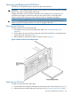
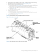

3. Slide the memory carrier assembly into the chassis until it begins to seat into the socket located
on the processor board.
CAUTION: Do not apply excessive force when closing the extraction handles and seating
the memory carrier assembly into the socket on the processor board. Manipulate the extraction
handles with care; failure to observe these cautions can result in damage to the extraction
handles and other server components.
4. Rotate the extraction handles inward and press the handles straight down until they snap into
the locked position.
5. Replace the memory carrier assembly cover and latch the top cover release lever closed. See
“Replacing the Memory Carrier Assembly Cover” (page 167).
6. If rack installed, slide the server completely into the rack. See “Inserting the Server into the
Rack” (page 164).
7. Reconnect the power cables and power on the server. See “Powering On the Server” (page 81).
Removing and Replacing System Memory
System memory, or DIMMs, are located on a pair of memory boards inside the memory carrier
assembly.
WARNING! Ensure that the system is powered off and all power sources have been disconnected
from the server prior to performing this procedure.
Voltages are present at various locations within the server whenever an AC power source is
connected. This voltage is present even when the main power switch is in the off position.
Failure to observe this warning can result in personal injury or damage to equipment.
CAUTION: Observe all ESD safety precautions before removing or replacing system memory.
Failure to follow ESD safety precautions can result in damage to the server.
Removing System Memory
To remove system memory, follow these steps:
1. Power off the server and disconnect the power cables. See “Powering Off the Server”
(page 82).
2. If rack installed, slide the server out from the rack until it stops. See “Extending the Server from
the Rack” (page 164).
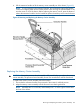
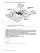
3. Unlatch the cover release lever on the top cover and remove the memory carrier assembly
cover. See “Removing the Memory Carrier Assembly Cover” (page 167).
NOTE: You do not need to fully remove the top cover to service this component; however,
the top cover release lever must be open. You must remove the memory carrier because it
attaches directly to the processor board.
4. Remove the memory carrier assembly. See “Removing the Memory Carrier Assembly”
(page 186).
NOTE: To avoid damage to the memory carrier extraction handles, HP recommends rotating
the handles inward and snapping them into the locked position when servicing the system
DIMMs or any time the carrier is out of the chassis. Before replacing the memory carrier, press
the button to release the extraction handles. Use the handles to replace the memory carrier
into the chassis.
5. To locate the DIMM you need to remove, use Figure 65: “8-DIMM Memory Carrier Board
Slot IDs” (page 192), or Figure 66: “24-DIMM Memory Carrier Board Slot IDs” (page 193).
188 Removing and Replacing Server Components