
HP Integrity rx3600 Server User Service Guide
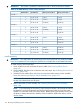

IMPORTANT: The number in parenthesis indicates the order in which the quads are loaded.
Table 76 24-DIMM Memory Carrier Loading Examples
Memory Carrier Side 1Memory Carrier Side 0Quad Slot IDsQuad Number
Example 1
2 GB (2)2 GB (1)0A 0B 0C 0D0
1 GB (4)1 GB (3)1A 1B 1C 1D1
512 MB (6)512 MB (5)2A 2B 2C 2D2
Example 2
1 GB (2)2 GB (1)0A 0B 0C 0D0
1 GB (3)512 MB (4)1A 1B 1C 1D1
512 MB (5)2A 2B 2C 2D2
Example 3
1 GB (2)2 GB (1)0A 0B 0C 0D0
512 MB (3)1A 1B 1C 1D1
512 MB (4)2A 2B 2C 2D2
Example 4
512 MB (2)2 GB (1)0A 0B 0C 0D0
512 MB (3)512 MB (5)1A 1B 1C 1D1
512 MB (4)512 MB (6)2A; 2B 2C 2D2
Installing Memory
IMPORTANT: You must pull the AC power plugs on the server every time you modify the DIMMs.
If you do not pull the AC power plugs, the system does not display the correct DIMM information.
To install memory, follow these steps:
1. Power off the server and disconnect the power cables. See “Powering Off the Server”
(page 82).
2. If rack installed, slide the server out from the rack until it stops. See “Extending the Server from
the Rack” (page 164).
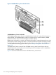
3. Unlatch the cover release lever on the top cover and remove the memory carrier assembly
cover. See “Removing the Memory Carrier Assembly Cover” (page 167).
NOTE: You do not need to fully remove the top cover to service this component; however,
the top cover release lever must be open.
4. Remove the memory carrier assembly. See “Removing the Memory Carrier Assembly”
(page 186).
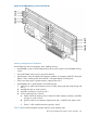
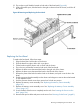
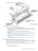
NOTE: To avoid damage to the memory carrier extraction handles, HP recommends rotating
the handles inward and snapping them into the locked position when servicing the system
DIMMs or any time the carrier is out of the chassis. Before replacing the memory carrier, press
the button to release the extraction handles. Use the handles to replace the memory carrier
into the chassis.
194 Removing and Replacing Server Components