
HP Integrity rx3600 Server User Service Guide
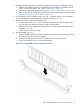
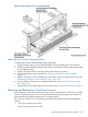

9. Replace the memory carrier assembly side cover.
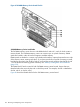
a. Insert the side cover tabs into the retaining slots at the base of the assembly (Figure 22).
b. Insert the tabs (Figure 63) into the slots on both sides of the extraction handle release
button until the side cover snaps into place.
NOTE: To install DIMMs into slots on the other side of the memory carrier, turn the carrier
over to the opposite side (side 0 or side 1) and repeat the installation procedure.
10. Replace the memory carrier assembly and latch the top cover release lever closed. See
“Replacing the Memory Carrier Assembly” (page 187).
11. If rack installed, slide the server completely into the rack. See “Inserting the Server into the
Rack” (page 164).
12. Reconnect the power cables and power on the server. See “Powering On the Server” (page 81).
Removing and Replacing the Front Bezel
The front bezel provides server control and port access, and LED interfaces. You must power off
the server to remove the front bezel.
NOTE: The procedures in this section see the upper portion of the front bezel; the lower portion
of the front bezel is the processor access door.
Removing the Front Bezel
To remove the front bezel, follow these steps:
1. Power off the server and disconnect the power cables. See “Powering Off the Server”
(page 82).
2. If rack installed, slide the server out from the rack until it stops. See “Extending the Server from
the Rack” (page 164).
3. Remove the memory carrier assembly cover. See “Removing the Memory Carrier Assembly
Cover” (page 167).
NOTE: You do not need to fully remove the top cover to service this component; however,
the top cover release lever must be open. You must remove the memory carrier because it
attaches directly to the processor board.
4. Remove the memory carrier assembly. See “Removing the Memory Carrier Assembly”
(page 186).
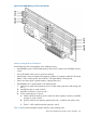
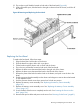
5. Press the button located on top of the bezel and directly in front of the memory carrier assembly
to release the processor board access door (Figure 68).
CAUTION: The processor board access door opens to approximately a 30 degree angle.
Do not force the door to open to a greater angle. Failure to observe this caution results in
damage to server components.
6. Use the processor board assembly access door as a handle and gently slide the assembly out
of the chassis approximately six inches.
7. Remove the six screws that attach the bezel to the chassis (Figure 68).
8. Tilt the bezel away from the chassis (Figure 68).
9. Remove the plastic server label located to the right of the front panel LEDs.
a. Grasp the label, and pull it out until it stops.
b. Lift up on the notched retaining tab at the rear of the label until it clears the slot.
c. Pull the label completely out of the chassis.
IMPORTANT: You must reinstall the plastic server label into the replacement bezel.
196 Removing and Replacing Server Components