
HP Integrity rx3600 Server User Service Guide

If the server has fewer than the maximum number of dual-core processors installed, install the
additional processor in the appropriate slot.
WARNING! Ensure that the system is powered off and all power sources have been disconnected
from the server prior to performing this procedure.
Voltages are present at various locations within the server whenever an AC power source is
connected. This voltage is present even when the main power switch is in the off position.
Failure to observe this warning can result in personal injury or damage to equipment.
CAUTION: Ensure that processor speed and cache size are identical for all processors. Failure
to observe this caution results in performance degradation or system failure.
The easiest way to ensure compatibility is to use dual-core processors with identical part numbers.
CAUTION: Observe all ESD safety precautions before attempting this procedure. Failure to follow
ESD safety precautions can result in damage to the server.
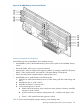
Processor Load Order
The server can have up to two dual-core processors on the processor board. The slots on the
processor board are labeled Module 0 and Module 1.
Table 77 lists the processor load sequence.
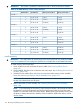
Table 77 Processor Load Order
SlotDual-Core Processor
Module 01
Module 12
Required Tools
To install and remove processors, use the processor install tool fastened to the processor board.
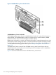
Removing a Dual-Core Processor
To remove a dual-core processor, follow these steps:
1. Power off the server and disconnect the power cables. See “Powering Off the Server”
(page 82).
2. If rack installed, slide the server out from the rack until it stops. See “Extending the Server from
the Rack” (page 164).
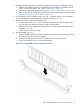
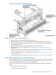
3. Remove the memory carrier assembly cover. See “Removing the Memory Carrier Assembly
Cover” (page 167).
NOTE: You do not need to fully remove the top cover to service this component; however,
the top cover release lever must be open. You must remove the memory carrier because it
attaches directly to the processor board.
4. Remove the memory carrier assembly. See “Removing the Memory Carrier Assembly”
(page 186).
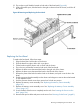
5. Remove the processor board assembly. See “Removing the Processor Board Assembly”
(page 198).
200 Removing and Replacing Server Components