
HP Integrity rx3600 Server User Service Guide
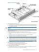
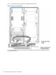
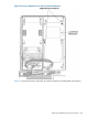
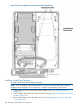
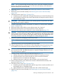
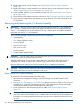
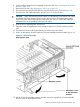
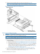
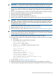
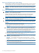

Figure 70 Processor Board Assembly
6. Open the processor cage (Figure 70).
a. Grasp the processor cage handle, and apply adequate force to rotate the handle upward.
b. Use the handle to rotate the cage closure approximately 90 degrees toward the front of
the assembly until it stops.
IMPORTANT: Ensure the processors are entirely exposed and can clear the cage closure for
removal.
7. Disconnect the processor power cable from the connector cable that attaches directly to the
processor board (Figure 71).
8. Unlock the processor from the socket on the processor board (Figure 72).
a. Unfasten the processor install tool (2.5-mm driver) from the tool holder on the processor
board.
b. Insert the processor tool into the hole that runs down the side of the heatsink.
c. Rotate the processor tool counterclockwise 180 degrees.
CAUTION: The zero insertion force (ZIF) socket for the processor is locked and unlocked
by half of a full turn of the processor install tool. The counterclockwise 180 degree rotation
(half turn) unlocks the socket. A clockwise 180 degree rotation locks the socket. Attempting
to turn the locking mechanism more than 180 degrees can severely damage the socket.
d. Refasten the processor install tool to the tool holder on the processor board.
9. Remove the dual-core processor from the processor slot.
a. Carefully grasp the sheet metal that encases the processor.
b. Pull the processor straight up and out of the chassis.
10. Protect the processor from damage.
a. Install the protective pin cover on the processor connectors to shield the connector pins.
b. Place the dual-core processor in an anti static container.
Removing and Replacing a Dual-Core Processor 201