
HP Integrity rx3600 Server User Service Guide

18. Replace the memory carrier assembly. See “Replacing the Memory Carrier Assembly”
(page 187).
19. Replace the memory carrier assembly cover and latch the top cover release lever closed. See
“Replacing the Memory Carrier Assembly Cover” (page 167).
20. If rack installed, slide the server completely into the rack. See “Inserting the Server into the
Rack” (page 164).
21. Reconnect the power cables and power on the server. See “Powering On the Server” (page 81).
22. Verify processor replacement and operation by using either the iLO 2 MP commands or the
EFI commands.
Removing and Replacing the I/O Board Assembly
IMPORTANT: The new version of the PCI/PCI-X/PCIe backplane (version 1.1) was shipped on
July 1, 2008. For existing servers, repair and replace should continue to be performed with the
version 1 I/O backplane. For servers shipped as of July 1, 2008, repair and replace should be
performed with version 1.1 I/O backplane.
The I/O board assembly contains the following server components:
• System battery
• I/O voltage regulator module
• Core I/O board
• LAN core I/O card
• SAS core I/O card
• PCI/PCI-X cards
• Trusted Platform Module (TPM)
WARNING! Ensure that the system is powered off and all power sources have been disconnected
from the server prior to performing this procedure.
Voltages are present at various locations within the server whenever an AC power source is
connected. This voltage is present even when the main power switch is in the off position.
Failure to observe this warning can result in personal injury or damage to equipment.
CAUTION: Observe all ESD safety precautions before attempting this procedure. Failure to follow
ESD safety precautions can result in damage to the server.
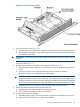
Removing the I/O Board Assembly
To remove the I/O board assembly, follow these steps:
1. Record the boot configuration settings. To find the settings, use the INFO ALL EFI Shell
command.
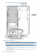
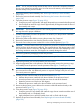
2. Use Figure 78: “TPM Location on I/O Board”, to determine if there is a TPM on the I/O board
assembly. If so, record the TPM settings to transfer to the replacement I/O board assembly.
See the HP-UX operating system documentation for instructions.
3. Power off the server and disconnect the power cables. See “Powering Off the Server”
(page 82).
CAUTION: The removal and replacement of the I/O board assembly occurs through the
rear of the rack for rack-installed servers. Carefully follow the board removal and replacement
procedures. You must first perform several tasks with the server extended out from the front of
the rack.
206 Removing and Replacing Server Components