
HP Integrity rx3600 Server User Service Guide
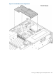
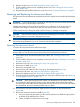
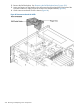

1. Insert the replacement card into the dedicated LAN core I/O slot.
a. Insert the tab at the base of the card bulkhead into the slot in the chassis.
b. Align the card connectors with the slots on the I/O board.
c. Apply firm, even pressure to both sides of the card until it fully seats into the slot.
2. Replace the slotted T15 screw that attaches the card bulkhead to the chassis; use a T15 driver
to turn the screw clockwise until it tightens to the chassis.
3. Replace the top cover. See “Replacing the Top Cover” (page 166).
4. If rack installed, slide the server completely into the rack. See “Inserting the Server into the
Rack” (page 164).
5. Reconnect all external cables to the card.
6. Reconnect the power cables and power on the server. See “Powering On the Server” (page 81).
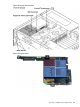
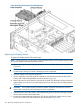
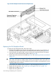
Removing and Replacing the Display Board
The display board is a combination board that supports the following server components:
• Power switch and status LEDs
• DVD drive
• Front panel USB port
• Diagnostic panel
The display board attaches to an interconnect board that functions as a link between the midplane
board and the display board.
The display board contains the power switch and the following status LEDs:
• Power LED
• System health LED
• Internal health LED
• External health LED
• Locator LED
For more detailed information about front panel LED behavior, see “Controls, Ports, and LEDs”
(page 28).
The display board includes a USB connector that supports USB 2.0 (480 Mbps).
The diagnostic panel provides failure identification for each component that has a detectable error
associated with it. For more information on the diagnostic panel LEDs, see “Controls, Ports, and
LEDs” (page 28).
WARNING! Ensure that the system is powered off and all power sources have been disconnected
from the server prior to performing this procedure.
Voltages are present at various locations within the server whenever an AC power source is
connected. This voltage is present even when the main power switch is in the off position.
Failure to observe this warning can result in personal injury or damage to equipment.
CAUTION: Observe all ESD safety precautions before attempting this procedure. Failure to follow
ESD safety precautions can result in damage to the server.
IMPORTANT: System information is stored on the display board assembly. You must write the
serial number and model string information to the new display board after installation.
Removing and Replacing the Display Board 221