
HP Integrity rx3600 Server User Service Guide

7. Install the diagnostic panel light guide (Figure 80).
a. Align the diagnostic panel light guide tabs with the slots on the display board.
b. Push down firmly on the light guide until it seats onto the board.
8. Replace the top two right-side bezel screws (Figure 80).
9. Replace the DVD drive. See “Replacing the DVD Drive” (page 185).
10. Reconnect the USB cable into the connector on the display board (Figure 80).
11. Replace the air baffle (Figure 83).
12. Replace the clear plastic cover.
13. Replace the top cover. See “Replacing the Top Cover” (page 166).
14. If rack installed, slide the server completely into the rack. See “Inserting the Server into the
Rack” (page 164).
15. Reconnect the power cables and power on the server. See “Powering On the Server” (page 81).
Removing and Replacing the SAS Backplane Board
Serial-attached SCSI (SAS) is a new, faster version of the industry standard SCSI technology.
Although SCSI is a proven technology, its parallel data communication model restricts it from
providing the speed and scalability required for modern data transfer and storage. In a parallel
data communication environment, multiple devices share one bus; all data travels over the same
cable and through the same port.
SAS provides serial, or point-to-point, data transfer. A point-to-point architecture means that each
device has its own private bus, cable, and port. This architecture improves the reliability and
availability of data, and greatly enhances data transfer rates. Current data transfer rates are 3
Gb/s. Additional features of the SAS technology include:
• Full-duplex capability (all data reads and writes occur simultaneously)
• Automatic device discovery and configuration (each device is assigned a unique SAS address)
• Thin cables and small connectors (assists with cooling and ease cable management issues)
• Increased scalability (expanders enable support for thousands of SAS devices)
The SAS backplane board attaches to an interconnect board that functions as a link between the
midplane board and the SAS backplane board.
WARNING! Ensure that the system is powered off and all power sources have been disconnected
from the server prior to performing this procedure.
Voltages are present at various locations within the server whenever an AC power source is
connected. This voltage is present even when the main power switch is in the off position.
Failure to observe this warning can result in personal injury or damage to equipment.
CAUTION: Observe all ESD safety precautions before attempting this procedure. Failure to follow
ESD safety precautions can result in damage to the server.
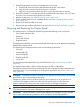
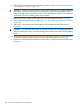
Removing the SAS Backplane Board
To remove the SAS backplane board, follow these steps:
1. Power off the server and disconnect the power cables. See “Powering Off the Server”
(page 82).
2. If rack installed, slide the server completely out from the rack. See “Extending the Server from
the Rack” (page 164).
3. Remove the top cover. See “Removing the Top Cover” (page 165).
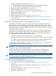
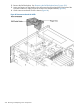
4. Remove the air baffle (Figure 83).
5. Remove the clear plastic cover.
Removing and Replacing the SAS Backplane Board 225