
HP Integrity rx3600 Server User Service Guide

2. If rack installed, slide the server completely out from the rack. See “Extending the Server from
the Rack” (page 164).
3. Remove the top cover. See “Removing the Top Cover” (page 165).
4. Remove the memory carrier assembly cover. See “Removing the Memory Carrier Assembly
Cover” (page 167).
5. Remove the clear plastic cover.
6. Remove the memory carrier assembly. See “Removing the Memory Carrier Assembly”
(page 186).
7. Remove the processor board. See “Removing the Processor Board Assembly” (page 198).
8. Remove hot-swappable chassis fan units 2 and 3. See “Removing a Hot-Swappable Chassis
Fan Unit” (page 168).
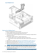
9. Remove the air baffle.
10. Disconnect the USB cable from the connector on the display board.
11. Remove the DVD drive. See “Removing the DVD Drive” (page 185).
12. Remove the display board. See “Removing the Display Board” (page 222).
13. Slide the SAS drives and fillers approximately two inches out of the drive bays. See “Removing
a Hot-Pluggable Disk Drive” (page 172).
CAUTION: When disconnecting the SAS cables, note the labeling on the cables. Both cables
and sockets are clearly marked with the correct channel. When reconnecting these cables,
match each cable with the appropriate socket on the SAS core I/O card. If the cables are
mismatched, the server operating system may not reboot.
14. Disconnect the SAS data and power cables from the connectors on the SAS backplane board.
15. Remove the SAS backplane board. See “Removing the SAS Backplane Board” (page 225).
16. Remove the interconnect board. See “Removing the Interconnect Board” (page 229).
17. Remove the I/O board assembly. See “Removing the I/O Board Assembly” (page 206).
18. Remove the power supplies. See “Removing a Hot-Swappable Power Supply” (page 170).
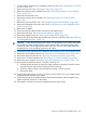
19. Remove the fan cables from the fan 1 and fan 2 housing units.
a. Push the release tab down and push the cable connector toward the front of the chassis
until the connector tabs clear the opening in the fan housing.
b. Guide the cable connector down through the opening in the fan housing.
c. Remove the cable.
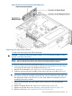
20. From the front of the server use a Torx 15 driver to remove the five Torx screws attaching the
midplane bracket assembly to the chassis.
21. Grasp the top edge of the midplane board sheet metal attachment and lift straight back to
release it from the guide pins on the chassis
22. Pull straight out and up to remove the midplane board from the chassis.
Removing and Replacing the Midplane Board 233