
HP Integrity rx3600 Server User Service Guide
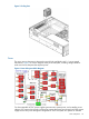
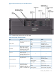
VAC and achieve 1+1 redundancy. The power supplies are power factor corrected and the
maximum DC power output of the power system is 1095 watts. Service the hot-swappable power
supplies are serviced by sliding them out the rear of the chassis.
Applying system power in normal customer usage, the rx3600 runs on 100 to 240 V. Standby
power will be supplied on either; hence the BMC will power up when the power supplies are
plugged in. The BPS0_AC_OK and BPS1_AC_OK signals indicate whether the AC voltage to the
power supplies is within the required range. If neither BPS0_AC_OK nor BPS1_AC_OK is asserted,
then the BMC should log an event and prevent the system from turning on.
Power Button
The Power button on the rx3600 is a momentary contact push button. The BMC polls the front
panel Power button at a rate of at least 2 Hz. The Power button is an input to the System Power
State Management. If the system is off, a single button press will turn on the system. If the system
has booted to an OS, and a short button press is detected, a graceful-shutdown request will be
sent to the system by pulsing ACPI_PWR_BTN_L; when the ACPI bits are set to note the O/S has
shut down, the BMC will perform a hard power down. If the system has not booted to an OS, or
if a long (five second) button press is detected, the system will do an immediate hard power off.
System Power State Management
The system power may be controlled from the Power button, an IPMI Chassis command,
Wake-On-LAN, loss or gain of AC.
Power On Sequence:
1. Update the cache of DIMM SPD information.
2. Ensure that the memory board is detected and that the cpu board has a processor in socket
0. If these FRUs are not detected the BMC logs an event against the Missing Device sensor
(sensor 0x15).
3. Check for a BPS0_AC_OK or a BPS1_AC_OK signal. If neither is asserted, then the AC supply
has a problem.
4. If any FRUs are missing or both AC supplies are not valid, then return to power off state.
5. Initialize I/O Expander settings prior to turning on power.
6. Set Power Sequencer Order. Set system frequency in Power Sequencer.
7. Pulse BMC_PWR_CMD to tell the Power Sequencer to enable the voltages in the system.
8. Wait for SEQ_MPON to know the power sequencer has finished and check if SEQ_STATUS=0
for a fault condition. If a fault has occurred, scan sensors for the cause and generate events.
9. Perform any pre-Reset Hardware Setup needed while power is on.
10. Release Reset by setting MPON=1.
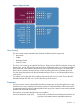
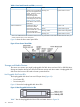
Front Display Panel, DVD, and Diagnostic Panel
The front display panel, DVD, and diagnostic panel are supported on a single board, called the
display board, located in the front of the chassis. Service the display board from the top of the
chassis.
The front display panel consists of the system status LEDs and a power switch. Use the front display
panel to determine the power status of the server, monitor the server as it progresses through the
boot cycle, and use the various LED states to assist with troubleshooting system problems.
A slimline DVD drive, or optional DVD+RW drive, is located above the hard disk drives in the
horizontal orientation of the front panel.
There is a USB 2.0 port positioned between the DVD drive and the front display panel.
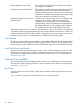
Each customer replaceable unit (CRU), with the exception of the power supplies, has a unique set
of status indicators located on a diagnostic panel that you view through the top cover. CRUs include
components such as individual memory DIMMs, processors, and fans. LEDs that correspond to
each CRU illuminate when there is a problem.
26 Overview