
Installation Guide, Seventh Edition - HP Integrity rx4640 Server


Installing Additional Components
Installing Internal Components
Chapter 3
50
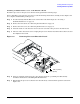
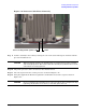
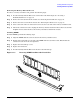
Installing the Memory Extender Board
To replace the memory extender board, perform the following steps:
Step 1. Ensure the extraction levers are positioned in the outward, unlocked position.
Step 2. Align the memory extender board with the left and right chassis guide slots.
Step 3. Slide the memory extender board in until it begins to seat in the socket located on the midplane
riser board.
Step 4. Push the extraction levers inward to the locked position in order to fully plug in the memory
extender board into the midplane riser board.
Step 5. Replace the front cover onto the chassis.
Step 6. Replace the front bezel onto the chassis.
Step 7. If rack-mounted, slide the HP server into the rack until it stops.
Installing PCI-X Cards
This section provides information on how to install additional PCI-X cards into your HP Integrity rx4640
server. The server supports PCI-X hot-plug technology and offers six PCI-X, hot-plug capable slots. For details
regarding PCI-X specifications, see “PCI-X Slot Locations and Configurations” below, or the HP Integrity
rx4640 User Service Guide for more detailed information. For procedures describing how to add, replace,
delete, and locate PCI-X cards, go to “Installing Additional PCI-X Cards” on page 53.
CAUTION There are restrictions on the number of PCI-X cards that can be installed in the rx4640 server
at any given time, depending on the cards being used.
Maximum quantity for any I/O configuration using 337972-B21, AB287A, or A9890A cards:
• Three 337972-B21 cards maximum plus three unpopulated slots
• Two AB287A cards maximum plus four unpopulated slots
• Three A9890A cards maximum plus three unpopulated slots
Failure to observe this caution results in server degradation, or server failure.
NOTE The PCI-X cards are hot-pluggable.
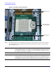
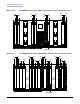
PCI-X Slot Locations and Configurations
PCI-X slots are numbered from 1 through 8 in the Server. Figure 3-16 shows the slot locations on the I/O
baseboard.
The following describes configuration requirements for slots 1 through 8:
• PCI slots 1 and 2 are dedicated for use by the core I/O cards—SCSI HBA card in slot 1 and Gigabyte
Ethernet LAN card in slot 2. Slots 1 and 2 are not hot-plug capable. Additional PCI-X expansion cards
cannot be placed in slots 1 or 2.