
User Service Guide, Third Edition - HP Integrity rx4640 Server
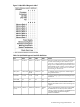
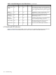
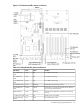
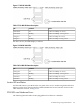
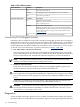
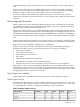
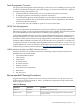
Table Of Contents
- HP Integrity rx4640 Server User Service Guide
- Table of Contents
- About This Document
- 1 Introduction
- 2 Controls, Ports, and LEDs
- 3 Powering Off and Powering On the Server
- 4 Removing and Replacing Components
- Safety Information
- Service Tools Required
- Accessing a Rack Mounted Server
- Accessing a Pedestal Mounted Server
- Removing and Replacing the Front Bezel
- Removing and Replacing the Front and Top Covers
- Removing and Replacing the Memory Extender Board
- Removing and Replacing Memory DIMMs
- Removing and Replacing the Processor Extender Board
- Removing and Replacing a Processor
- Removing and Replacing Hot-Swappable Chassis Fans
- Removing and Replacing the I/O Baseboard
- Removing and Replacing Hot-Pluggable PCI-X Cards
- Removing and Replacing OLX Dividers
- Removing and Replacing Core I/O Cards
- Removing and Replacing the Server Battery
- Removing and Replacing Hard Disk Drives
- Removing and Replacing the SCSI Backplane Board
- Removing and Replacing the Midplane Riser Board
- Removing and Replacing the Power Supplies
- Removing and Replacing the Power Distribution Board
- Removing and Replacing the DVD Drive
- Removing and Replacing the DVD I/O Board
- Removing and Replacing the Display Board
- Removing and Replacing the QuickFind Diagnostic Board
- 5 Troubleshooting
- Troubleshooting Tips
- Possible Problems
- Troubleshooting Using LED Indicators
- Diagnostics
- Recommended Cleaning Procedures
- Where to Get Help
- A Parts Information
- B Booting the Operating System
- Operating Systems Supported on HP Integrity Servers
- Configuring System Boot Options
- Booting and Shutting Down HP-UX
- Booting and Shutting Down HP OpenVMS
- Booting and Shutting Down Microsoft Windows
- Booting and Shutting Down Linux
- C Utilities
- Extensible Firmware Interface Boot Manager
- EFI/POSSE Commands
- Specifying SCSI Parameters
- Using the Boot Configuration Menu
- Index
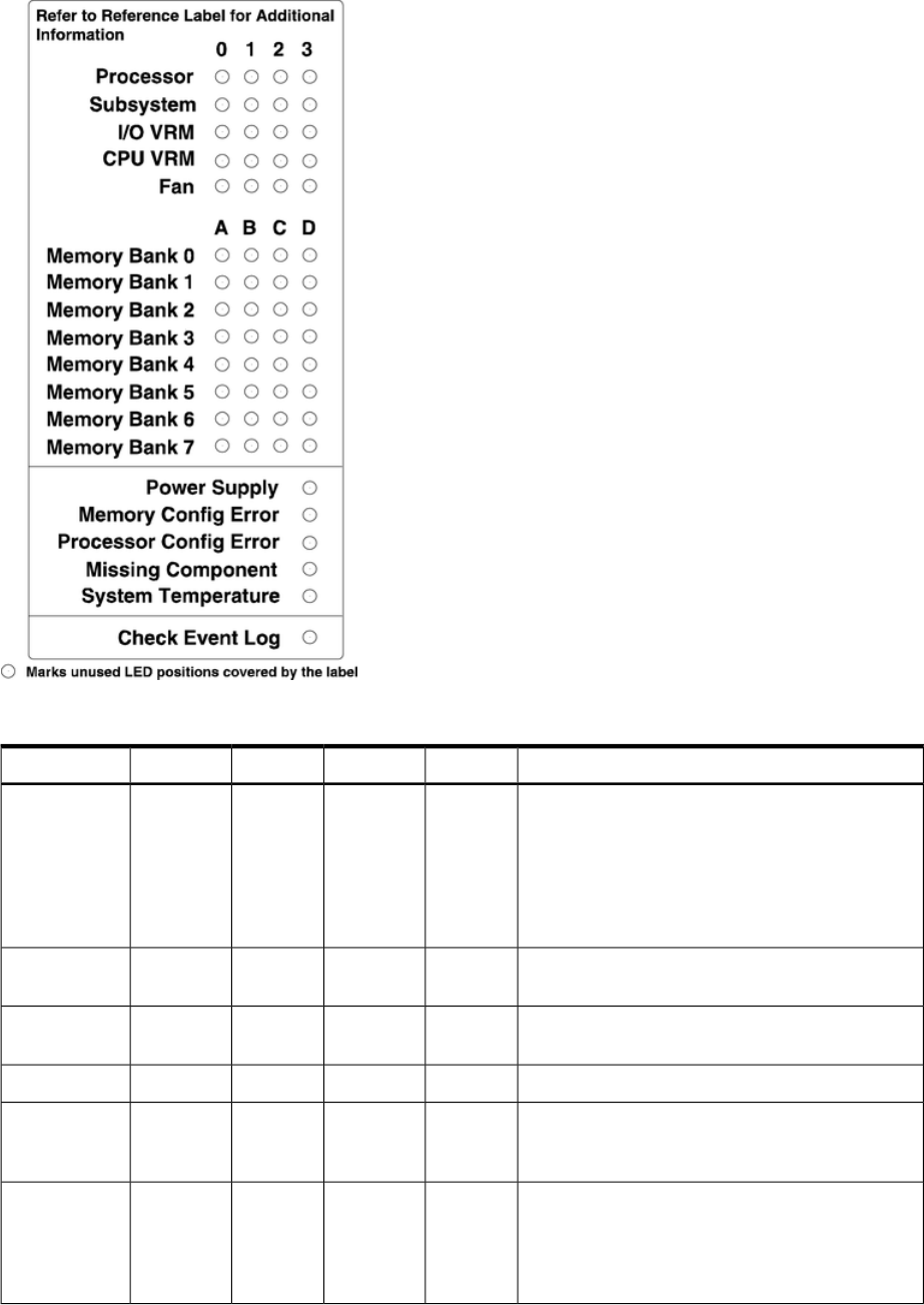
Figure 5-4 QuickFind Diagnostic Label
Table 5-4 QuickFind Diagnostic Panel LED Definitions
DetailsLED3LED 2LED 1LED 0Item
If the Server LED (on front panel) is in the attention
or fault state and the processor LED is on, the
processor or voltage regulator has failed. Replace
the processor module in the specified socket. If the
thermal LED is in the warning or critical state and
the processor LED is on, the processor exceeded
the warning or critical level.
Socket 3Socket 2Socket 1Socket 0Processor
A soldered voltage regulator has failed. Replace
the specified board.
n/aI/O boardMemory
board
CPU boardSubsystem
A plug-in voltage regulator has failed. Replace I/O
baseboard.
n/a3 volt5 volt12 voltI/O VRM
n/an/an/an/an/aCPU VRM
One or both fans in a fan module have failed.
Replace the module. Fan 2 is in front of the power
supplies.
n/a210Fan Module
The specified DIMM has failed. Replace the DIMM.
If all the LEDs for a rank (0-7) are lit, and the
memory config error LED is lit, the DIMMs in the
specified rank are mismatched. Replace
mismatched DIMMs.
DIMM
xD
DIMM xCDIMM xBDIMM xAMemory Bank
X (0-7)
Troubleshooting Using LED Indicators 101