
User Service Guide, Third Edition - HP Integrity rx4640 Server
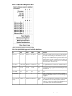
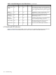
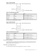
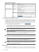
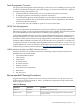
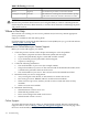
Table Of Contents
- HP Integrity rx4640 Server User Service Guide
- Table of Contents
- About This Document
- 1 Introduction
- 2 Controls, Ports, and LEDs
- 3 Powering Off and Powering On the Server
- 4 Removing and Replacing Components
- Safety Information
- Service Tools Required
- Accessing a Rack Mounted Server
- Accessing a Pedestal Mounted Server
- Removing and Replacing the Front Bezel
- Removing and Replacing the Front and Top Covers
- Removing and Replacing the Memory Extender Board
- Removing and Replacing Memory DIMMs
- Removing and Replacing the Processor Extender Board
- Removing and Replacing a Processor
- Removing and Replacing Hot-Swappable Chassis Fans
- Removing and Replacing the I/O Baseboard
- Removing and Replacing Hot-Pluggable PCI-X Cards
- Removing and Replacing OLX Dividers
- Removing and Replacing Core I/O Cards
- Removing and Replacing the Server Battery
- Removing and Replacing Hard Disk Drives
- Removing and Replacing the SCSI Backplane Board
- Removing and Replacing the Midplane Riser Board
- Removing and Replacing the Power Supplies
- Removing and Replacing the Power Distribution Board
- Removing and Replacing the DVD Drive
- Removing and Replacing the DVD I/O Board
- Removing and Replacing the Display Board
- Removing and Replacing the QuickFind Diagnostic Board
- 5 Troubleshooting
- Troubleshooting Tips
- Possible Problems
- Troubleshooting Using LED Indicators
- Diagnostics
- Recommended Cleaning Procedures
- Where to Get Help
- A Parts Information
- B Booting the Operating System
- Operating Systems Supported on HP Integrity Servers
- Configuring System Boot Options
- Booting and Shutting Down HP-UX
- Booting and Shutting Down HP OpenVMS
- Booting and Shutting Down Microsoft Windows
- Booting and Shutting Down Linux
- C Utilities
- Extensible Firmware Interface Boot Manager
- EFI/POSSE Commands
- Specifying SCSI Parameters
- Using the Boot Configuration Menu
- Index

Power Supply Status LED Indicators
Each of the two 200-240 VAC power supply unit has three status LEDs located on the back of
the power supply on the rear panel. Consolidated status of all power supplies is reported by the
front control panel by the power status LED.
Figure 5-6 Power Supply Status LED
Table 5-6 Power Supply Status LED
StatusFail LED-AmberPredict Fail
LED-Amber
Power
LED-Green
No AC power applied to all PSUsOffOffOff
No AC power applied to this PSU onlyOnOffOff
AC present/standby outputs onOffOffBlinking
PSU DC outputs on and OKOffOffOn
Power supply failureOnOffOff
Predictive failure—PSU about to fail because of poorly
performing fan
OffBlinkingOn
Current limit on 48 VDC outputBlinkingOffOn
iLO MP LAN Port Link/Activity LED Display
The iLO MP LAN uses an RJ-45 type connector. This connector has two LEDs (LAN link and
LAN activity) that signal status and activity.
Two versions of the iLO MP card exist for this server. Depending on which version of the card
is installed in the server, the iLO MP LAN port LEDs display differently.
On some servers, the LEDs display as follows:
104 Troubleshooting