
User Service Guide, Third Edition - HP Integrity rx4640 Server
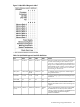
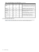
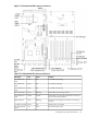
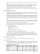
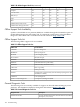
Table Of Contents
- HP Integrity rx4640 Server User Service Guide
- Table of Contents
- About This Document
- 1 Introduction
- 2 Controls, Ports, and LEDs
- 3 Powering Off and Powering On the Server
- 4 Removing and Replacing Components
- Safety Information
- Service Tools Required
- Accessing a Rack Mounted Server
- Accessing a Pedestal Mounted Server
- Removing and Replacing the Front Bezel
- Removing and Replacing the Front and Top Covers
- Removing and Replacing the Memory Extender Board
- Removing and Replacing Memory DIMMs
- Removing and Replacing the Processor Extender Board
- Removing and Replacing a Processor
- Removing and Replacing Hot-Swappable Chassis Fans
- Removing and Replacing the I/O Baseboard
- Removing and Replacing Hot-Pluggable PCI-X Cards
- Removing and Replacing OLX Dividers
- Removing and Replacing Core I/O Cards
- Removing and Replacing the Server Battery
- Removing and Replacing Hard Disk Drives
- Removing and Replacing the SCSI Backplane Board
- Removing and Replacing the Midplane Riser Board
- Removing and Replacing the Power Supplies
- Removing and Replacing the Power Distribution Board
- Removing and Replacing the DVD Drive
- Removing and Replacing the DVD I/O Board
- Removing and Replacing the Display Board
- Removing and Replacing the QuickFind Diagnostic Board
- 5 Troubleshooting
- Troubleshooting Tips
- Possible Problems
- Troubleshooting Using LED Indicators
- Diagnostics
- Recommended Cleaning Procedures
- Where to Get Help
- A Parts Information
- B Booting the Operating System
- Operating Systems Supported on HP Integrity Servers
- Configuring System Boot Options
- Booting and Shutting Down HP-UX
- Booting and Shutting Down HP OpenVMS
- Booting and Shutting Down Microsoft Windows
- Booting and Shutting Down Linux
- C Utilities
- Extensible Firmware Interface Boot Manager
- EFI/POSSE Commands
- Specifying SCSI Parameters
- Using the Boot Configuration Menu
- Index
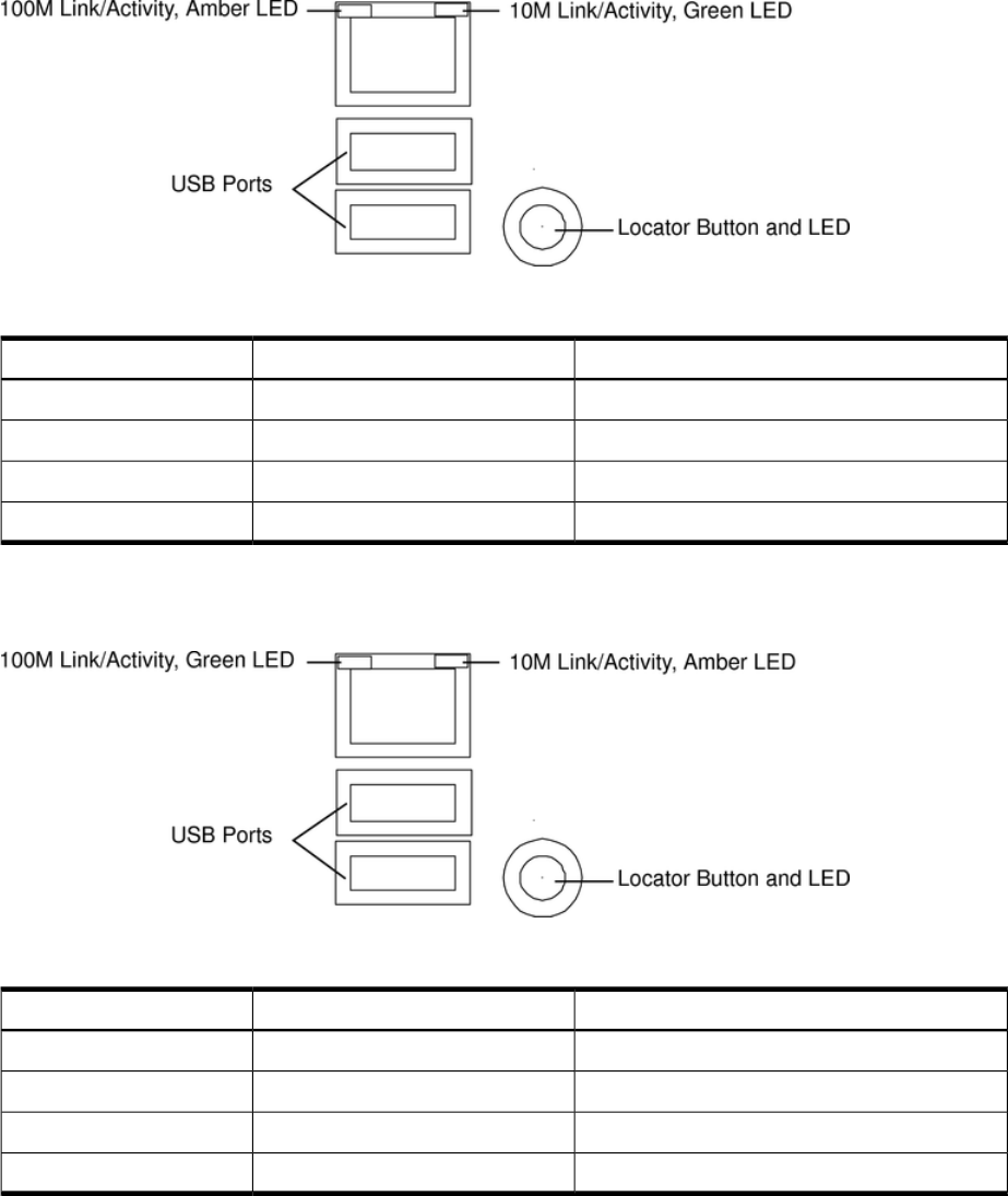
Figure 5-7 iLO MP LAN LEDs
Table 5-7 iLO MP LED Status Description
StatusConditionLED
Linked at 100MBps. No activityOn100M amber
Linked at 100MBps. Activity presentBlinking100M amber
Linked at 10MBps. No activityOn10M green
Linked at 10MBps. Activity presentBlinking10M green
On other servers, the LEDs display as follows:
Figure 5-8 iLO MP LAN LEDs
Table 5-8 iLO MP LED Status Description
StatusConditionLED
Linked at 100MBps. No activityOn100M green
Linked at 100MBps. Activity presentBlinking100M green
Linked at 10MBps. No activityOn10M amber
Linked at 10MBps. Activity presentBlinking10M amber
Locator LED and Button
An LED and button is provided on the rear panel of the server. Another single blue LED and
button is on the front control panel that enables/disables the locator function. For the locator
LED and button location, see Figure 5-7.
PCI-X LEDs and Hardware Errors
The following table describes the hot-pluggable PCI-X LED error conditions.
Troubleshooting Using LED Indicators 105