
User Service Guide, Third Edition - HP Integrity rx4640 Server
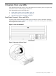
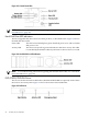
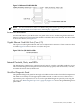
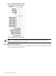


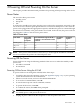
Table Of Contents
- HP Integrity rx4640 Server User Service Guide
- Table of Contents
- About This Document
- 1 Introduction
- 2 Controls, Ports, and LEDs
- 3 Powering Off and Powering On the Server
- 4 Removing and Replacing Components
- Safety Information
- Service Tools Required
- Accessing a Rack Mounted Server
- Accessing a Pedestal Mounted Server
- Removing and Replacing the Front Bezel
- Removing and Replacing the Front and Top Covers
- Removing and Replacing the Memory Extender Board
- Removing and Replacing Memory DIMMs
- Removing and Replacing the Processor Extender Board
- Removing and Replacing a Processor
- Removing and Replacing Hot-Swappable Chassis Fans
- Removing and Replacing the I/O Baseboard
- Removing and Replacing Hot-Pluggable PCI-X Cards
- Removing and Replacing OLX Dividers
- Removing and Replacing Core I/O Cards
- Removing and Replacing the Server Battery
- Removing and Replacing Hard Disk Drives
- Removing and Replacing the SCSI Backplane Board
- Removing and Replacing the Midplane Riser Board
- Removing and Replacing the Power Supplies
- Removing and Replacing the Power Distribution Board
- Removing and Replacing the DVD Drive
- Removing and Replacing the DVD I/O Board
- Removing and Replacing the Display Board
- Removing and Replacing the QuickFind Diagnostic Board
- 5 Troubleshooting
- Troubleshooting Tips
- Possible Problems
- Troubleshooting Using LED Indicators
- Diagnostics
- Recommended Cleaning Procedures
- Where to Get Help
- A Parts Information
- B Booting the Operating System
- Operating Systems Supported on HP Integrity Servers
- Configuring System Boot Options
- Booting and Shutting Down HP-UX
- Booting and Shutting Down HP OpenVMS
- Booting and Shutting Down Microsoft Windows
- Booting and Shutting Down Linux
- C Utilities
- Extensible Firmware Interface Boot Manager
- EFI/POSSE Commands
- Specifying SCSI Parameters
- Using the Boot Configuration Menu
- Index
NOTE: For troubleshooting information regarding the DVD LEDs, see “DVD/DVD-R/DVD-RW
Drive LED Indicators” (page 100).
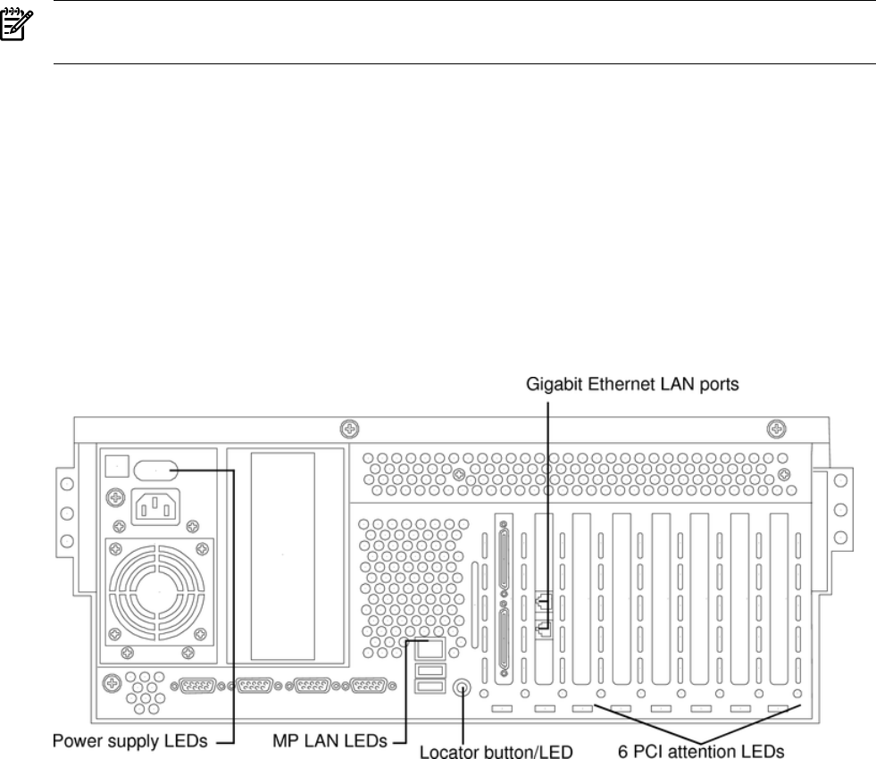
Rear Panel Controls, Ports, and LEDs
The server rear panel includes communication ports, I/O ports, AC power connectors, two power
supply bays, attention LED indicators for the hot-pluggable PCI boards, and the locator
LED/button. Figure 2-6 shows the LEDs located on the rear panel of the server. They include the
following:
• Power supplies
• iLO MP LAN
• 2 port Gigabit ethernet card LAN
• PCI slots 3-8
Figure 2-6 Rack Mount and Pedestal Rear View
Power Supply Status LEDs
Each 200-240 VAC power supply unit has three status LEDs located on the power supply accessible
from the rear panel. Consolidated status of all power supplies is reported by the front control
panel by the power status LED. Figure 2-7 shows the location of the power supply status LEDs
on the rear of the enclosure.
Rear Panel Controls, Ports, and LEDs 23