
User Service Guide, Third Edition - HP Integrity rx4640 Server
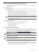
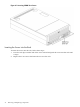
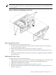
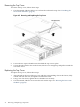
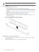
Table Of Contents
- HP Integrity rx4640 Server User Service Guide
- Table of Contents
- About This Document
- 1 Introduction
- 2 Controls, Ports, and LEDs
- 3 Powering Off and Powering On the Server
- 4 Removing and Replacing Components
- Safety Information
- Service Tools Required
- Accessing a Rack Mounted Server
- Accessing a Pedestal Mounted Server
- Removing and Replacing the Front Bezel
- Removing and Replacing the Front and Top Covers
- Removing and Replacing the Memory Extender Board
- Removing and Replacing Memory DIMMs
- Removing and Replacing the Processor Extender Board
- Removing and Replacing a Processor
- Removing and Replacing Hot-Swappable Chassis Fans
- Removing and Replacing the I/O Baseboard
- Removing and Replacing Hot-Pluggable PCI-X Cards
- Removing and Replacing OLX Dividers
- Removing and Replacing Core I/O Cards
- Removing and Replacing the Server Battery
- Removing and Replacing Hard Disk Drives
- Removing and Replacing the SCSI Backplane Board
- Removing and Replacing the Midplane Riser Board
- Removing and Replacing the Power Supplies
- Removing and Replacing the Power Distribution Board
- Removing and Replacing the DVD Drive
- Removing and Replacing the DVD I/O Board
- Removing and Replacing the Display Board
- Removing and Replacing the QuickFind Diagnostic Board
- 5 Troubleshooting
- Troubleshooting Tips
- Possible Problems
- Troubleshooting Using LED Indicators
- Diagnostics
- Recommended Cleaning Procedures
- Where to Get Help
- A Parts Information
- B Booting the Operating System
- Operating Systems Supported on HP Integrity Servers
- Configuring System Boot Options
- Booting and Shutting Down HP-UX
- Booting and Shutting Down HP OpenVMS
- Booting and Shutting Down Microsoft Windows
- Booting and Shutting Down Linux
- C Utilities
- Extensible Firmware Interface Boot Manager
- EFI/POSSE Commands
- Specifying SCSI Parameters
- Using the Boot Configuration Menu
- Index
4 Removing and Replacing Components
This chapter describes the procedure for removing and replacing the different components in
the HP Integrity rx4640 server.
Safety Information
To ensure safe handling of components and to prevent harm to you and the server, follow the
procedures listed below:
• Use an antistatic wrist strap and a grounding mat, such as those included in the Electrically
Conductive Field Service Grounding Kit (HP 9300-1155).
• Handle accessory boards and components by the edges only. Do not touch any metal-edge
connectors or any electrical components on accessory boards.
• Do not wear clothing subject to static charge build-up, such as wool or synthetic materials.
WARNING! Hazardous voltages are present inside the server. Always remove AC power
from the server and associated assemblies while working inside the unit. Serious injury can
result if this warning is not observed.
Service Tools Required
Service of this product could require one or more of the following tools:
• Electrically conductive field service kit (P/N 9300-1155)
• 1/4 inch flat blade screwdriver
• ACX-15 torx screwdriver
• ACX-25 torx screwdriver
Accessing a Rack Mounted Server
The HP Integrity rx4640 server is designed to be rack mounted. The following procedure explains
how to gain access to your server that is mounted in an approved rack. For rack installation
instructions, review the document titled Installation Guide, Mid-Weight Slide Kit, 5065-7291. This
document is on the HP website at: http://www.hp.com/racksolutions.
WARNING! Ensure that all anti-tip features (front and rear anti-tip feet installed; adequate
ballast properly placed; and so on) are employed prior to extending the server.
Extending the Server From the Rack
NOTE: Ensure that there is enough area (approximately 1.5 meters [4.5 ft]) to fully extend the
server out the front and work on it.
To extend the server from the rack, follow these steps:
1. Remove the T-25 screws that fasten the server to the rack. See Figure 4-1.
2. Flip out the two pull handles at either end of the front bezel and slowly pull the unit forward
by the handles. The server is fully extended when the rail clips are locked in place. When
fully extended, the front and top covers are fully accessible.
Safety Information 31