
User Service Guide, Third Edition - HP Integrity rx4640 Server
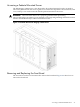
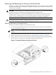
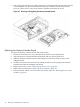
Table Of Contents
- HP Integrity rx4640 Server User Service Guide
- Table of Contents
- About This Document
- 1 Introduction
- 2 Controls, Ports, and LEDs
- 3 Powering Off and Powering On the Server
- 4 Removing and Replacing Components
- Safety Information
- Service Tools Required
- Accessing a Rack Mounted Server
- Accessing a Pedestal Mounted Server
- Removing and Replacing the Front Bezel
- Removing and Replacing the Front and Top Covers
- Removing and Replacing the Memory Extender Board
- Removing and Replacing Memory DIMMs
- Removing and Replacing the Processor Extender Board
- Removing and Replacing a Processor
- Removing and Replacing Hot-Swappable Chassis Fans
- Removing and Replacing the I/O Baseboard
- Removing and Replacing Hot-Pluggable PCI-X Cards
- Removing and Replacing OLX Dividers
- Removing and Replacing Core I/O Cards
- Removing and Replacing the Server Battery
- Removing and Replacing Hard Disk Drives
- Removing and Replacing the SCSI Backplane Board
- Removing and Replacing the Midplane Riser Board
- Removing and Replacing the Power Supplies
- Removing and Replacing the Power Distribution Board
- Removing and Replacing the DVD Drive
- Removing and Replacing the DVD I/O Board
- Removing and Replacing the Display Board
- Removing and Replacing the QuickFind Diagnostic Board
- 5 Troubleshooting
- Troubleshooting Tips
- Possible Problems
- Troubleshooting Using LED Indicators
- Diagnostics
- Recommended Cleaning Procedures
- Where to Get Help
- A Parts Information
- B Booting the Operating System
- Operating Systems Supported on HP Integrity Servers
- Configuring System Boot Options
- Booting and Shutting Down HP-UX
- Booting and Shutting Down HP OpenVMS
- Booting and Shutting Down Microsoft Windows
- Booting and Shutting Down Linux
- C Utilities
- Extensible Firmware Interface Boot Manager
- EFI/POSSE Commands
- Specifying SCSI Parameters
- Using the Boot Configuration Menu
- Index
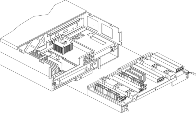
5. Pull on the extraction levers to unplug the memory extender board from the socket located
on the midplane riser board and remove the memory extender board from the chassis.
Figure 4-7 shows how to remove the memory extender board from the server.
Figure 4-7 Removing and Replacing the Memory Extender Board
Replacing the Memory Extender Board
To replace the memory extender board, follow these steps:
1. Ensure the extraction levers are positioned in the outward, unlocked position.
2. Align the memory extender board with the front and rear chassis guide slots.
3. Slide the memory extender board in until it begins to seat in the socket located on the
midplane board.
4. Push the extraction levers inward to the locked position in order to plug in the memory
extender board into the midplane riser board.
5. Replace the front cover. See “Replacing the Front Cover” (page 35).
6. Replace the front bezel. See “Replacing the Front Bezel” (page 34).
7. If rack mounted, slide the server into the rack until it stops. See “Inserting the Server into
the Rack” (page 32).
38 Removing and Replacing Components