
User Service Guide, Third Edition - HP Integrity rx4640 Server
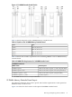
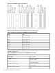
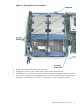
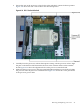
Table Of Contents
- HP Integrity rx4640 Server User Service Guide
- Table of Contents
- About This Document
- 1 Introduction
- 2 Controls, Ports, and LEDs
- 3 Powering Off and Powering On the Server
- 4 Removing and Replacing Components
- Safety Information
- Service Tools Required
- Accessing a Rack Mounted Server
- Accessing a Pedestal Mounted Server
- Removing and Replacing the Front Bezel
- Removing and Replacing the Front and Top Covers
- Removing and Replacing the Memory Extender Board
- Removing and Replacing Memory DIMMs
- Removing and Replacing the Processor Extender Board
- Removing and Replacing a Processor
- Removing and Replacing Hot-Swappable Chassis Fans
- Removing and Replacing the I/O Baseboard
- Removing and Replacing Hot-Pluggable PCI-X Cards
- Removing and Replacing OLX Dividers
- Removing and Replacing Core I/O Cards
- Removing and Replacing the Server Battery
- Removing and Replacing Hard Disk Drives
- Removing and Replacing the SCSI Backplane Board
- Removing and Replacing the Midplane Riser Board
- Removing and Replacing the Power Supplies
- Removing and Replacing the Power Distribution Board
- Removing and Replacing the DVD Drive
- Removing and Replacing the DVD I/O Board
- Removing and Replacing the Display Board
- Removing and Replacing the QuickFind Diagnostic Board
- 5 Troubleshooting
- Troubleshooting Tips
- Possible Problems
- Troubleshooting Using LED Indicators
- Diagnostics
- Recommended Cleaning Procedures
- Where to Get Help
- A Parts Information
- B Booting the Operating System
- Operating Systems Supported on HP Integrity Servers
- Configuring System Boot Options
- Booting and Shutting Down HP-UX
- Booting and Shutting Down HP OpenVMS
- Booting and Shutting Down Microsoft Windows
- Booting and Shutting Down Linux
- C Utilities
- Extensible Firmware Interface Boot Manager
- EFI/POSSE Commands
- Specifying SCSI Parameters
- Using the Boot Configuration Menu
- Index
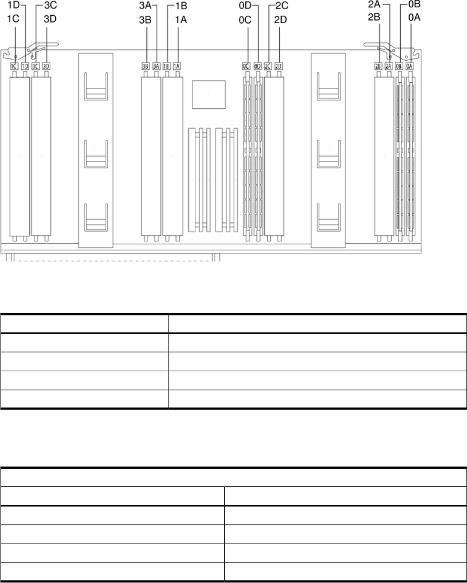
Figure 4-9 16 DIMM Extender Board Slot IDs
Table 4-1 details the quads on the 16 DIMM memory extender board.
Table 4-1 Quads on the 16 DIMM Memory Extender Board
SlotsQuad
Slots 0A, 0B, 0C, 0DQuad 0
Slots 1A, 1B, 1C, 1DQuad 1
Slots 2A, 2B, 2C, 2DQuad 2
Slots 3A, 3B, 3C, 3DQuad 3
Table 4-2 details the slot filler requirements when installing DIMMs on the 16 DIMM memory
extender board.
Table 4-2 DIMM Filler Requirements for 16 DIMM Extender Board
16 DIMM Extender Board
Fillers Required
1
DIMMs Loaded
6 fillers total: 2 fillers in quads 1, 2, and 3 (all quads filled)4 DIMMs in quad 0
4 fillers total: 2 fillers in quads 2 and 3 (all quads filled)8 DIMMs in quads 0 and 1
2 fillers total: 2 fillers in quads 3 (all quads filled)12 DIMMs in quads 0, 1, and 2
No fillers required16 DIMMs in quads 0, 1, 2, and 3
1 One DIMM filler board covers two adjacent DIMM slots.
32 DIMM Memory Extender Board Layout
The following details the slot locations, quads, and slot filler requirements on the optional 32
DIMM memory extender board.
Figure 4-10 shows the slot locations on the optional 32 DIMM extender board.
Removing and Replacing Memory DIMMs 41