
User Service Guide, Third Edition - HP Integrity rx4640 Server
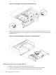
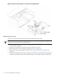
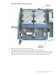
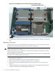
Table Of Contents
- HP Integrity rx4640 Server User Service Guide
- Table of Contents
- About This Document
- 1 Introduction
- 2 Controls, Ports, and LEDs
- 3 Powering Off and Powering On the Server
- 4 Removing and Replacing Components
- Safety Information
- Service Tools Required
- Accessing a Rack Mounted Server
- Accessing a Pedestal Mounted Server
- Removing and Replacing the Front Bezel
- Removing and Replacing the Front and Top Covers
- Removing and Replacing the Memory Extender Board
- Removing and Replacing Memory DIMMs
- Removing and Replacing the Processor Extender Board
- Removing and Replacing a Processor
- Removing and Replacing Hot-Swappable Chassis Fans
- Removing and Replacing the I/O Baseboard
- Removing and Replacing Hot-Pluggable PCI-X Cards
- Removing and Replacing OLX Dividers
- Removing and Replacing Core I/O Cards
- Removing and Replacing the Server Battery
- Removing and Replacing Hard Disk Drives
- Removing and Replacing the SCSI Backplane Board
- Removing and Replacing the Midplane Riser Board
- Removing and Replacing the Power Supplies
- Removing and Replacing the Power Distribution Board
- Removing and Replacing the DVD Drive
- Removing and Replacing the DVD I/O Board
- Removing and Replacing the Display Board
- Removing and Replacing the QuickFind Diagnostic Board
- 5 Troubleshooting
- Troubleshooting Tips
- Possible Problems
- Troubleshooting Using LED Indicators
- Diagnostics
- Recommended Cleaning Procedures
- Where to Get Help
- A Parts Information
- B Booting the Operating System
- Operating Systems Supported on HP Integrity Servers
- Configuring System Boot Options
- Booting and Shutting Down HP-UX
- Booting and Shutting Down HP OpenVMS
- Booting and Shutting Down Microsoft Windows
- Booting and Shutting Down Linux
- C Utilities
- Extensible Firmware Interface Boot Manager
- EFI/POSSE Commands
- Specifying SCSI Parameters
- Using the Boot Configuration Menu
- Index
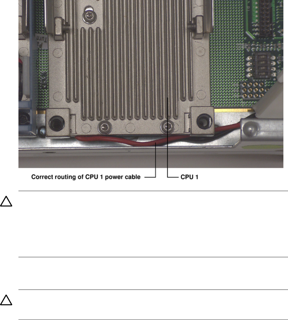
Figure 4-17 Processor Cable Routed Correctly
CAUTION: Test the alignment of the assembly to the socket by gently moving the assembly
back and forth with the palm of your hand—you should feel little or no side play. However,
because the assembly is not yet tightened, it may tilt slightly toward the center of the extender
board—this is acceptable.
Before locking the processor assembly into its socket, ensure that the power cable is not
pinched between the heatsink and sheet metal frame of the extender board. For the correct
placement of the processor power cable, see Figure 4-17.
9. Insert the 2 mm hex end of the processor installation tool through the processor into the ZIF
socket lock. Rotate the socket 180 degrees clockwise to lock the processor to the processor
extender board.
CAUTION: When rotating the locking cam, hold the palm of your hand on top of the
assembly and exert light pressure. This ensures that the assembly stays flush and level to
the socket while it is being tightened.
50 Removing and Replacing Components